Abstract
Activated TIG welding process enables full penetration in a single pass in tubular joints of wall thickness up to 8 mm just with a square butt joint preparation. It eliminates the need for J groove type edge preparation. It gives improved productivity as the weld is completed in a single pass with improved quality and lesser heat input.
In order to reduce the lead time in joining tube to tube joints of boiler components which will be subjected to high pressure and temperature conditions Activated TIG (ATIG) welding process was established for joining tube butt joints of carbon and low alloy steel.
Keywords:ATIG, pressure parts, boilers
1. Introduction
At present welding of tube to tube joints of boiler is carried out by conventional TIG welding process. It requires J groove edge preparation for the tubes and two or three passes to complete the joint depending on the thickness. It necessitates a relatively high proportion of handling and welding time in the entire fabrication process. This affects the productivity and production on the shop floor. The arc time per weldment is high. Besides, the filler wire, shielding gases and power consumption are also high.
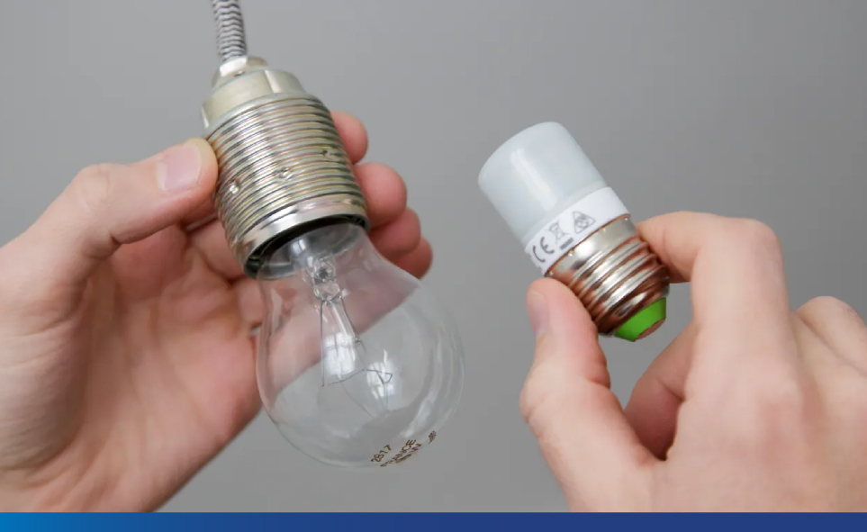
Activated TIG is a new technology wherein the application of a special flux on the weld seam of the base metal significantly increases the weld penetration. Application of ATIG welding enables single-sided full penetration tube butt joints to be made with just square butt joint preparation.
2. Activated TIG (ATIG) Welding
The increased weld penetration in ATIG welding is attributed to the reverse Marangoni effect. Marangoni effect is one of the penetration mechanisms, which refer to the convective flow within the weld pool due to the surface tension gradient on the weld pool surface. During TIG welding the surface tension gradient is negative and the convection movements are centrifugal leading to shallow penetration. The addition of activated flux induces an inversion of the convection currents changing the sign of the surface tension gradient, resulting in convection movements changing to centripetal. Hence, the penetration depth increases.
3. Experimental studies
Studies have been carried out to check the technological feasibility of the ATIG process for welding of low alloy steel [SA213 T22] tubular joints for pressure parts application. These experiments have been carried out using the orbital welding machine. Low alloy steel tubes are welded with activated flux assisted orbital TIG welding equipment and also the dissimilar material combination of low alloy steels are successfully welded.
The surfaces of the tubes to be joined are cleaned to remove oxide films, oil coatings, etc. After ensuring, the right fit-up of the square edge prepared tube joints, the activated flux paste (mixture prepared with flux powder and acetone) is applied to the joint area by using a smooth brush. The flux that is applied here has major elements such as silica, titanium, aluminium, iron, calcium, manganese, nickel, chromium and copper. These elements can be in oxide form or fluoride forms. On applying the flux on the joint area, shielding gas, suitable welding current, welding voltage, welding speed, wire feed rate, gas flow rate, torch angle, torch position, polarity is set to appropriate to the material and wall thickness so that full penetration is obtained in a single pass.
The welding is carried out in keeping the tubes stationary and rotating the head around the job to complete the joint.
The welding process parameters adopted during the conventional and activated flux assisted TIG weld joints with pure argon shielding gas. The TIG torch was maintained at slow travel speeds of 3 m/min and fewer welding currents during activated flux assisted TIG welding (ATIG) when compared to conventional TIG welding. The wire feed rate is much lesser in ATIG welding compared to conventional TIG welding.
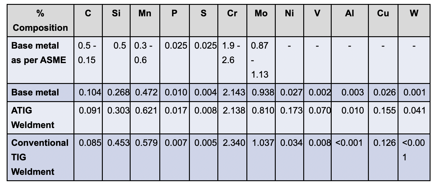
The chemical composition in flux and non-flux regions of TIG welding are within the range of the ASME standard requirements.
4. Results & discussion
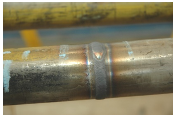
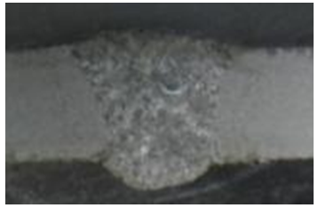
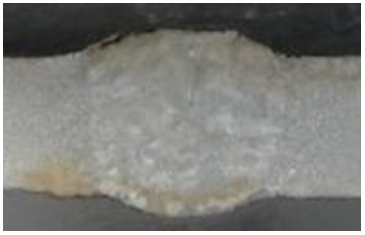
A typical tube to tube butt joint welded by ATIG welding is shown in Figure 4.1. The macrographs of conventional TIG and ATIG welded joints are shown in Figure 4.2 and Figure. 4.3. It can be observed that the weld reinforcement is very uniform in all positions of the tubular joint. The weld penetration is complete in a single pass with a uniform under bead profile in ATIG welded joints.
weldment
The micrographs of T22 weldment for conventional TIG welding, shows ferrite and bainite phases and whereas the ATIG weldment shows more bainitic structure in the weld as shown in Figure. 4.4 & Figure. 4.5
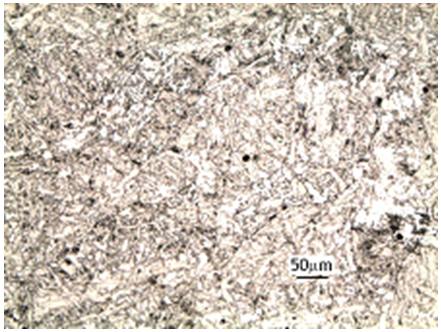
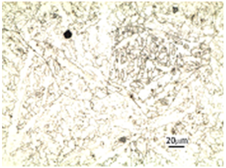
Fig. 4.4 Micrographs of T22 Weld in Conventional Orbital TIG welding
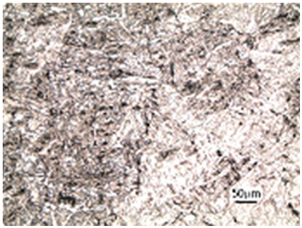
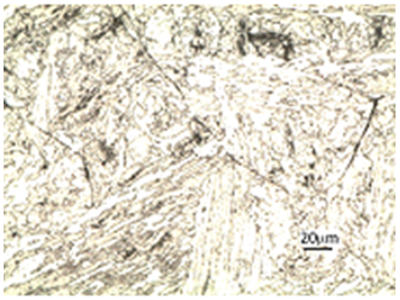
Fig. 4.5 Micrographs of T22 Weld in Activated Orbital TIG welding
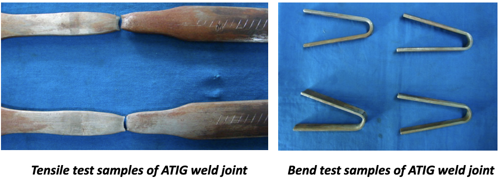
The integrity of weld joints and weld metal properties evaluated through Real-Time Radiography (RTR), Radiography Test (RT), Transverse tensile test, guided bend test (root and face), hardness micro & macro examinations are found to meet ASME standard requirements and is shown in Table 4.1. Figure. 4.6 shows the tested specimens.
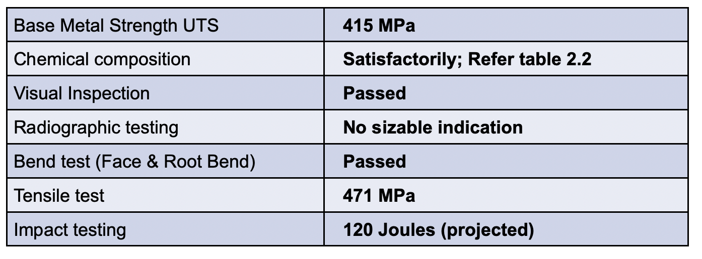
The tensile test requirement as per ASME is minimum 415 MPa and the results of activated TIG-welded T22 tubular joints meeting the requirement.
To understand the voltage-current characteristics with conventional TIG and ATIG the current and voltage waveforms, shown in Figure 4.7 (a) & (b), were obtained by using the arc weld monitoring system during ATIG welding trial.
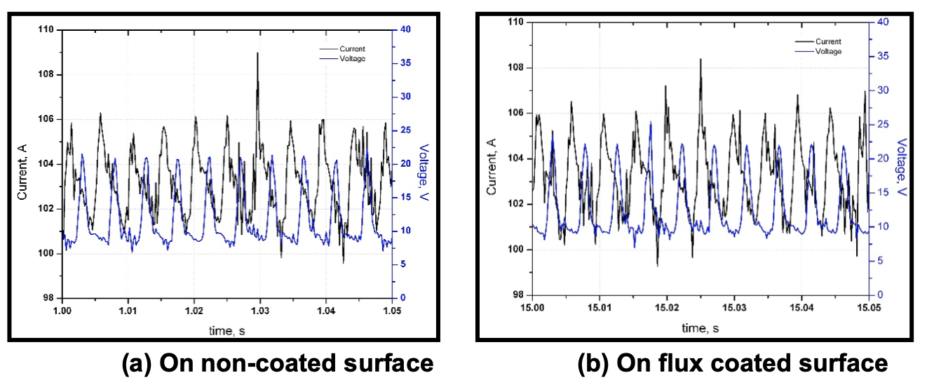
It is interesting to note that as the TIG arc moves from non-coated surface to flux coated surface the arc voltage increases significantly. Further, the arc voltage is much more stable when the arc runs on the flux coated surface than on the uncoated metal surface as is evident from Figure. 4.7 (b).
Conclusions
- The ATIG welding is able to provide full penetration welds in a single pass in square butt joints of tubes with wall thickness up to 8.0 mm, which is not possible in the conventional TIG welding process
- The ATIG welding is found to produce radiographic quality welds and complete bainite phase in the low alloy steel [T22] weld metal. The weld metal deposited by ATIG is found to meet all mechanical properties viz. tensile, bend, hardness requirements as per ASME standards
- The productivity of tube joints is increased by three times per shift in ATIG welding compared to the conventional TIG welding method. The consumption of power, shielding gas and the consumable wire came down to approx. 50%
- The current and voltage signature analysis also prove that the ATIG process results in more stable voltage and increased voltage
References
- The experiences of activated tungsten inert gas (ATIG) welding applied on 1.4301 type stainless steel plates T. Sándor&JánosDobránszky
- New Perspectives of flux assisted GTA Welding in titanium structures, N perry, SMarya, B.S.L. Industries, Soissons
- Weld pool characteristics of the ATIG-Welded Joints, Janos Dobranszky, Research group for metals technology of the Hungarian academy of sciences, Hungary
- Evaluation of the Activated TIG Welding Process for Fossil Boiler Tube Applications –Dr. A Raja and N Rajasekaran
Shri N Rajasekaran, PVD Ramesh, A. Santhakumari & Dr. A. Raja


Pushpendrasinh
January 30, 2022 at 4:41 pmIs Recvarment as a tig welding?