Name: R. S. Jha
Thermax Ltd.
Head of Innovation
Name: Pramod Mallikarjun Shigarkanthi
Thermax Ltd.
Senior Manager- Engineering
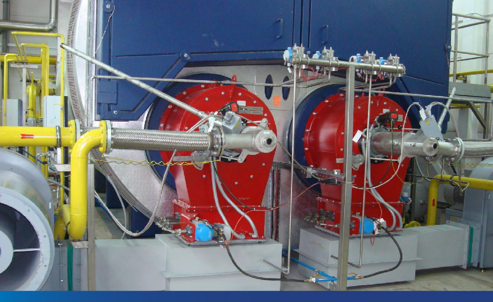
Failure modes of the boiler
- Higher membrane stress
- Higher stress concentration
- Exposure to higher temperatures (Water level control)
- Poor water quality
- Thermal stress
- Overheating
- Poor circulation/ Dry-out
- Erosion
- Corrosion
- Overfiring
IBR 1950 and EN 12953-3 (2016) comparison:
| IBR 1950 | EN 12953-3 (2016) |
| As per IBR 1950, in an integral furnace boiler, for both oil and gas fuel, the Maximum heat input in a single furnace is limited to 12 MW | As per EN12953-3(2016), in an integral furnace boiler, the maximum heat input in a single furnace is limited to 18 MW for oil fuel and 23.4 MW for gas fuel. Higher heat input has been derived from the calculation of heat flux corresponding to the design metal temperature of the furnace for the minimum diameter and length of the furnace. Higher heat input for the gas-fired boiler has been deduced from the non-luminous radiation and lower heat flux of a gas-fired boiler. Lower heat transfer in the gas-fired boiler is considered in the calculation of tube wall temperature. Boilers with heat input between 14 to 18 MW for fuel oil and heat input between 18.2 to 23.4 for gas require detailed calculations of heat flux and metal temperature. |
| Maximum furnace diameter < 1800 mm | Maximum furnace diameter < 2000 mm It allows furnace diameter up to 2000 mm, but it requires stress calculation by FEA. |
| No constraints on stiffener ring pitch and position. | It constrains the use of stiffeners in high heat flux zone |
| Does not specify the Minimum required furnace length for the given furnace heat input | EN12953-3(2016), Figure no. 2 specifies the Minimum required furnace length for given furnace heat input |
For Boilers with heat input between 14 to 18 MW for fuel oil and heat input between 18.2 to 23.4 for gas, EN 12953-3(2016) mandates additional operating requirements as listed below:
- More stringent operating conditions must be specified such as improved water quality requirements in addition to the requirements of EN 12953-10:2003, shorter maintenance and/or inspection intervals.
- Temperature monitoring of the furnace shell
- Monitoring of the conductivity of the boiler water shall be in accordance with EN 12953-6:2011, improvement in the circulation during start-up.
- More stringent start-up conditions such as limitation of the heating rate in the cold start-up
Boiler design-Metal temperature calculation
- Allowable stress calculation
- Thermal stress calculation
- Heat generation
- Heat transfer area (Furnace diameter & length)
- Heat flux calculation
- Luminous vs non-luminous flame
- Tube wall temperature- velocity
- Tube plate temperature (velocity and ligament)
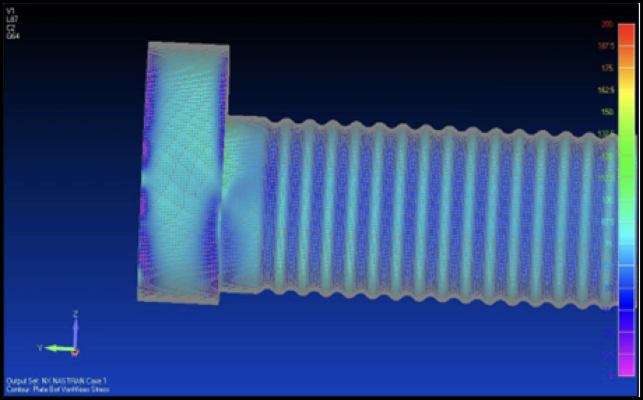
Boiler design – Thermal stress
- The same tube plate connected with the furnace, first pass convective tubes, second pass convective tubes & boiler shell
- These surfaces are exposed to different temperature conditions
- Differential thermal expansion
- Thermal stress
- Higher tensile stress in tubes or shells near to furnace due to higher expansion and rigidity of the furnace
- Compression stress in the furnace due to lower thermal expansion of neighbouring tubes and shell
- Compression stress in tubes near the shell due to lower thermal expansion of the shell
Thermal stress – Furnace design
- Higher breathing space for stiffener furnace as it can’t absorb differential expansion (EN)
- The minimum distance between the tube plate and the stiffener to avoid stiffener in the high-temperature zone (EN)
- A consequence of furnace failure is very high in stiffener furnaces as it can damage the tube plate section
Thermal stress – Furnace design
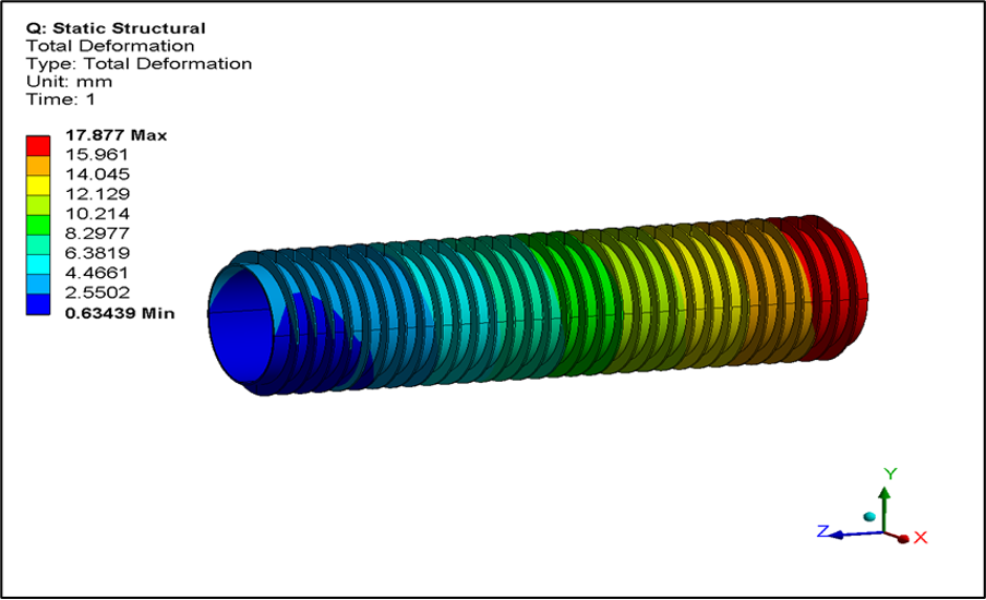
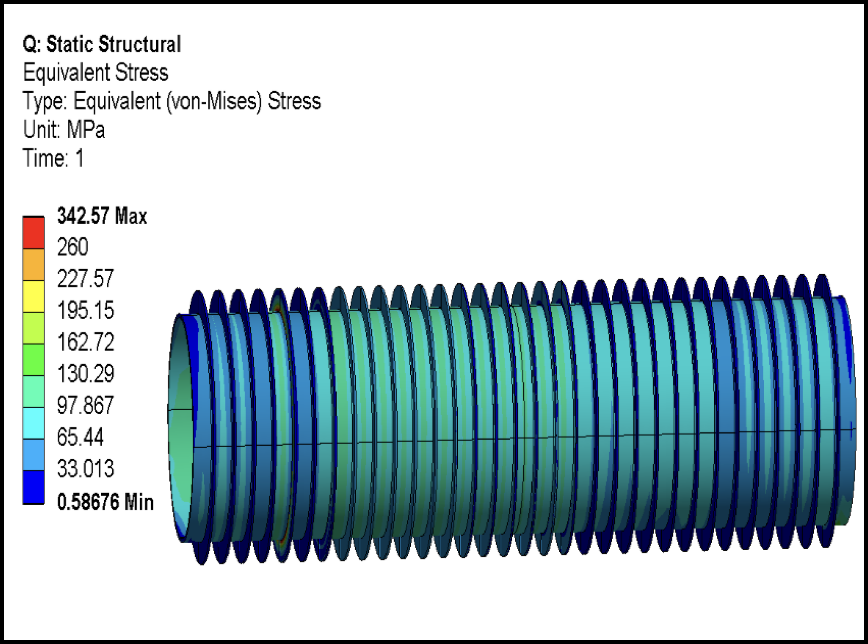
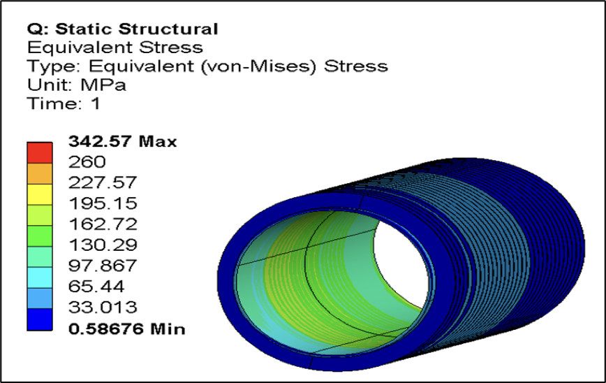
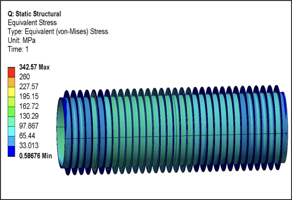
Stiffener furnace vs Corrugated furnace stress comparison
Thermal stress – Furnace design
Stiffener furnace vs Corrugated furnace stress comparison
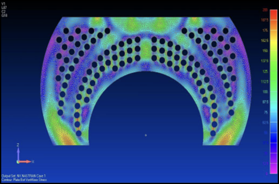
Thermal stress – Breathing space

Differential expansion can be the reason for high stress in the lower tube
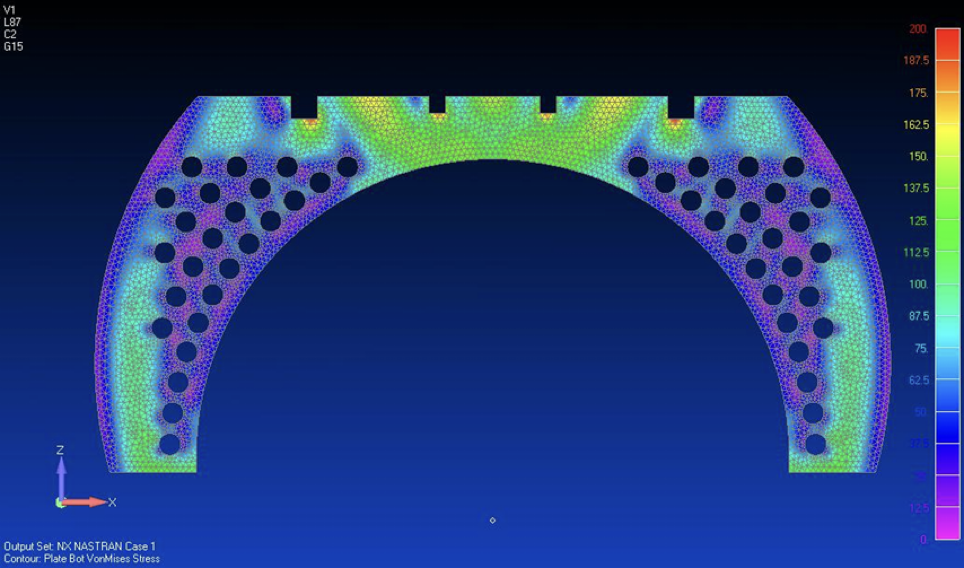
Higher stress in tubes near to shell
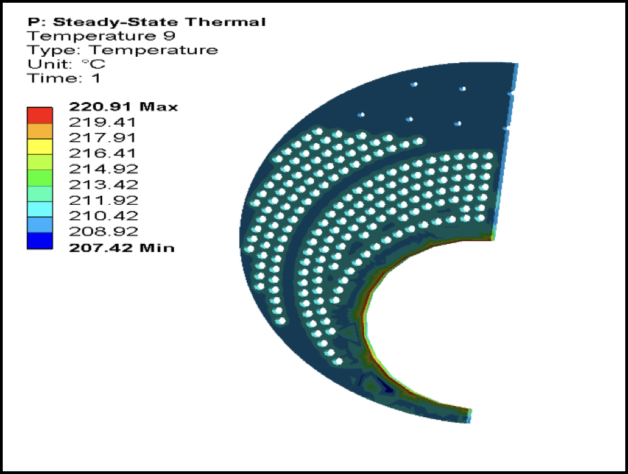
Tube plate cracking – Temperature profile on the tube plate
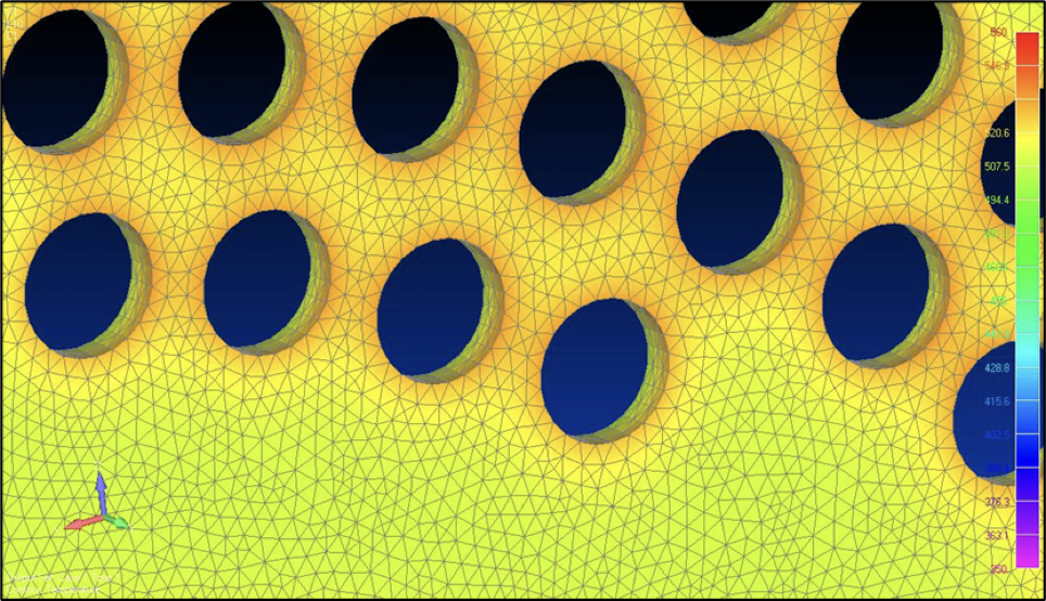
Influencing parameters
- Furnace exit temperature
- Fuel- luminous vs non-luminous flame
- Velocity
- Ligament
- Constraints on velocity
- Increase in ligament
- Conversion from oil to gas – case study
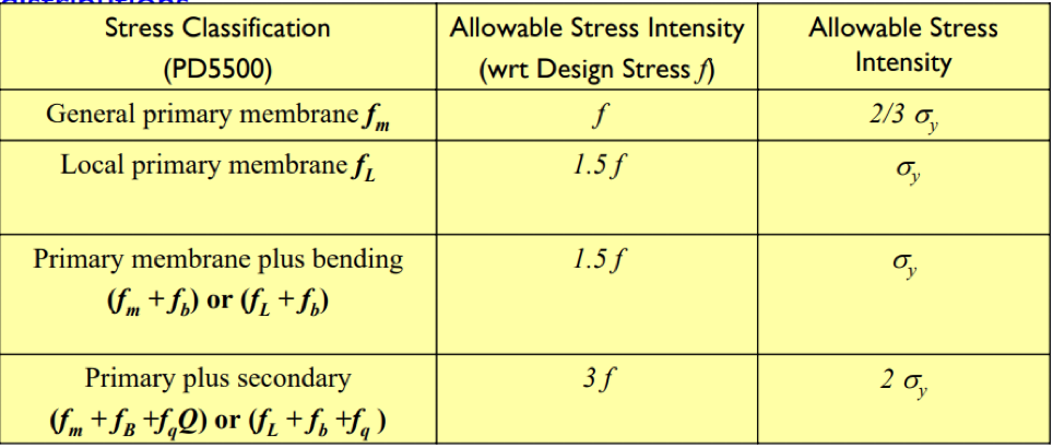
Stresses in the boiler
- Membrane stress (Pm)
- Local membrane stress -membrane stress including discontinuity (PL)
- Bending stress (Pb)
- Secondary membrane plus bending including thermal stress (Q)
- Peak (F)
Design by formula
- Primary membrane stress (Pm)
- Bending stress (Pb)
Design by Analysis
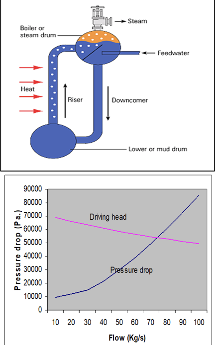
Boiler design – Circulation
- Natural circulation
- Circulation ratio
- Driving head & flow resistance
Failure mode
- Departure from nucleate boiling
- Flow regime and void fraction
- Phase stratification
- Two-phase flow instability
Design criteria
- Tube entry velocity (flow stratification limit on mass flow rate, tube inclination)
- Void fraction (percentage of steam by volume in a steam water mixture)
- Steam quality at the outlet (Dry-out, Critical heat flux)
Circulation design – Flow regime
- Subcooled boiling
- Saturated nucleate boiling (bubbles distributed in complete tube cross-section)
- Saturated forced convective boiling (Annular flow or annular mist flow)
- Post-dry-out (mist flow)
Circulation design – A void fraction
- Void fraction (steam volume fraction)
- Void fraction as an indicator of flow regime
- Void fraction as a design criteria
Circulation design – Departure from nucleate boiling
- Critical heat flux (> 4 X 10 5 W/m2)
- Critical mass flux (< 4 X 10 5 W/m2)
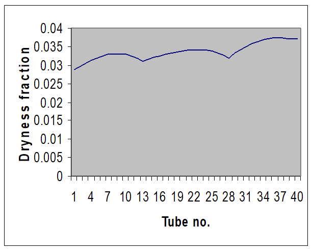
Dryness fraction as a function of mass flux
Circulation design – Phase stratification
- Phase stratification – phase separation with smooth interface under gravity.
- It can induce dry-out
- Minimum entry velocity
- Factor affecting stratification
- Inclination angle (0° / 10°)
- Steam quality (critical mass flux)
- Common area – IBH tubes, the top section of MP tubes
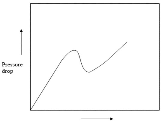
Circulation design – Two-phase flow Instability
- Flow oscillation
- Poor circulation ratio & higher dryness fraction
- Accelerate dry-out process
- Cyclic loading
Circulation design – Maldistribution
- Common circulation ratio
- Maldistribution
- Merging & Separation
- Momentum
- Uneven heat transfer
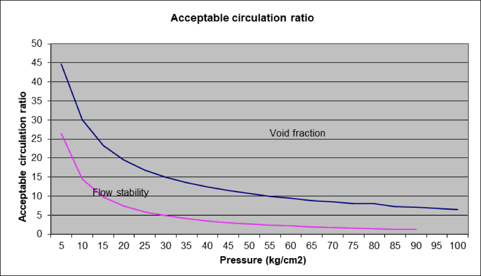
Circulation design – Circulation ratio
- Circulation ratio as a design criteria
- Void fraction & two-phase flow instability
- Effect of pressure on design circulation ratio
Boiler design – Erosion
- Erosion is a primary function of flue gas velocity, relative hardness of ash particles and collision angle
- This can be expressed as follows: 𝐸 = 𝑘𝑓(𝜃)𝑣𝑛
- Where K is the function of the relative hardness of heat transfer surface and ash
- Erosion in IBH, convective tubes, heat recovery units, dust collection equipment
- Role of velocity in erosion
- Velocity constraints in water tube design and fire tube design
- A soot blower may induce erosion in the boiler
- The design velocity has become lower with time to improve the reliability of the boiler
- Role of circulation in erosion
Boiler design – Corrosion
- High-temperature corrosion
- Low-temperature corrosion
High-temperature corrosion – Fuel oil
- Vanadium attack
Saturation temperature for V2O5- 600°C & Na2SO4 – 700 to 800°C
V2O5 in presence of Na2SO4 (Sodium Vanadate)
- Absorbs ambient oxygen and supply to metal
- Removes protective layer of iron oxide
- Sulphide attack by Na2SO4 (liberated Sulphur reacts with metal, Na2CO3 formed)
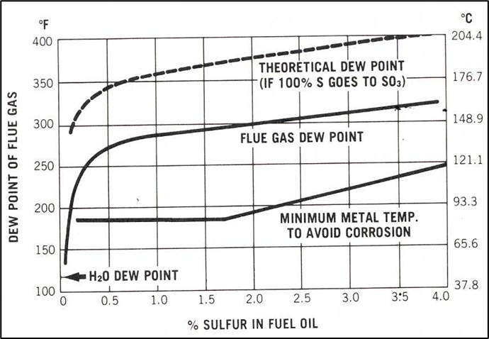
Low-temperature corrosion – Fuel oil
- Low-end corrosion
- Condensation of sulfuric acid at the heat transfer surface (Governed by the sulfuric acid dew point temp. and metal temp
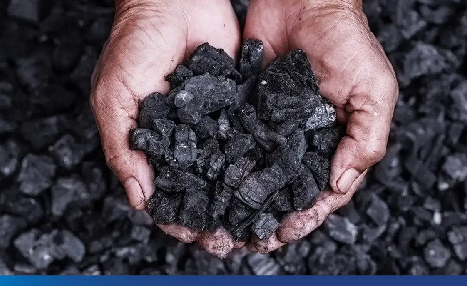
Corrosion – Solid fuel
- The first and second layers are formed by melting Na2SO4 and K2SO4.
- As the deposition surface is wet with molten salt, deposition of salt and flies ash takes place.
- As the thickness increases, temperature increases and goes beyond the saturation temperature and only fly ash gets deposited
- The deposited Na2SO4 and Fe2O3 reacts with flue-gas SO3 and forms complex Na2Fe(SO4)3
- This lower melting point reacts with Fe
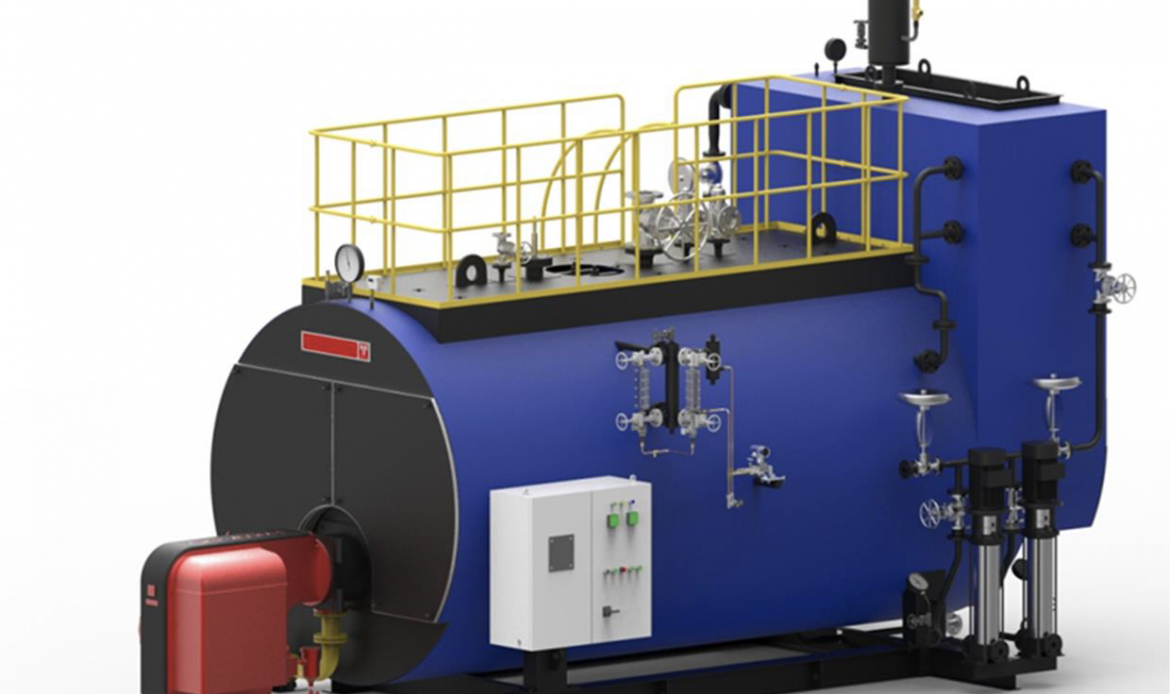
Our key products
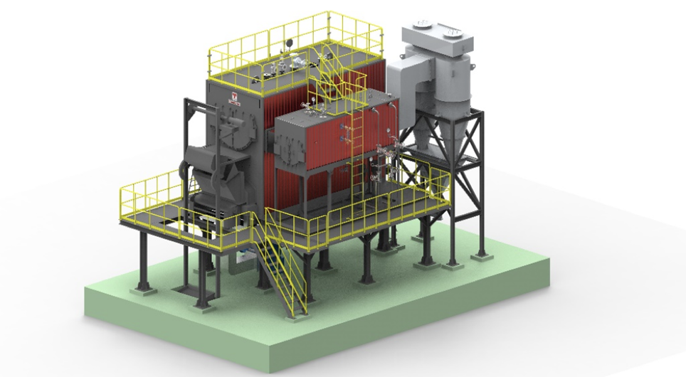
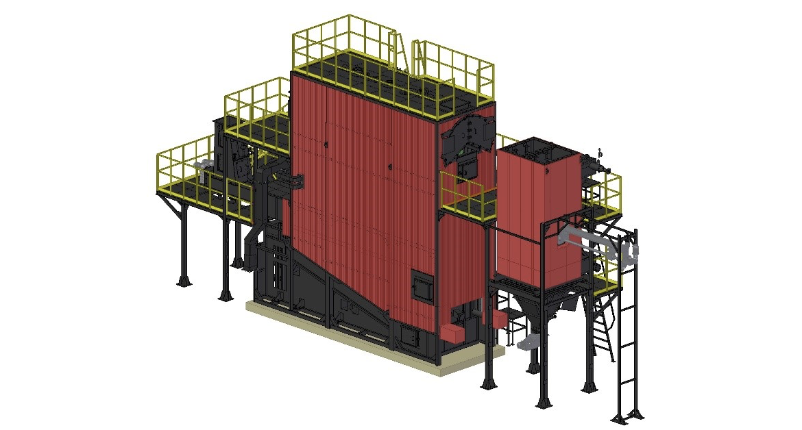
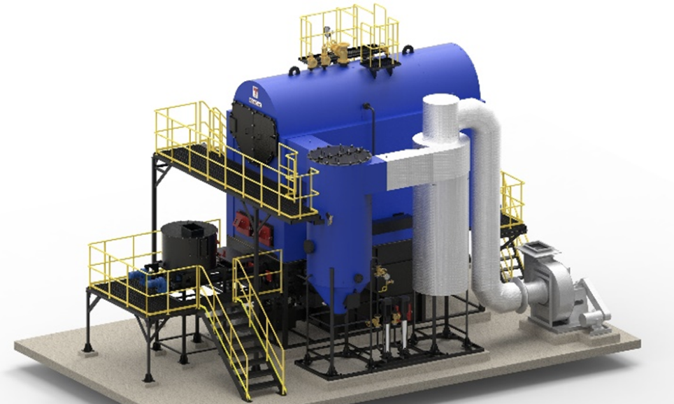
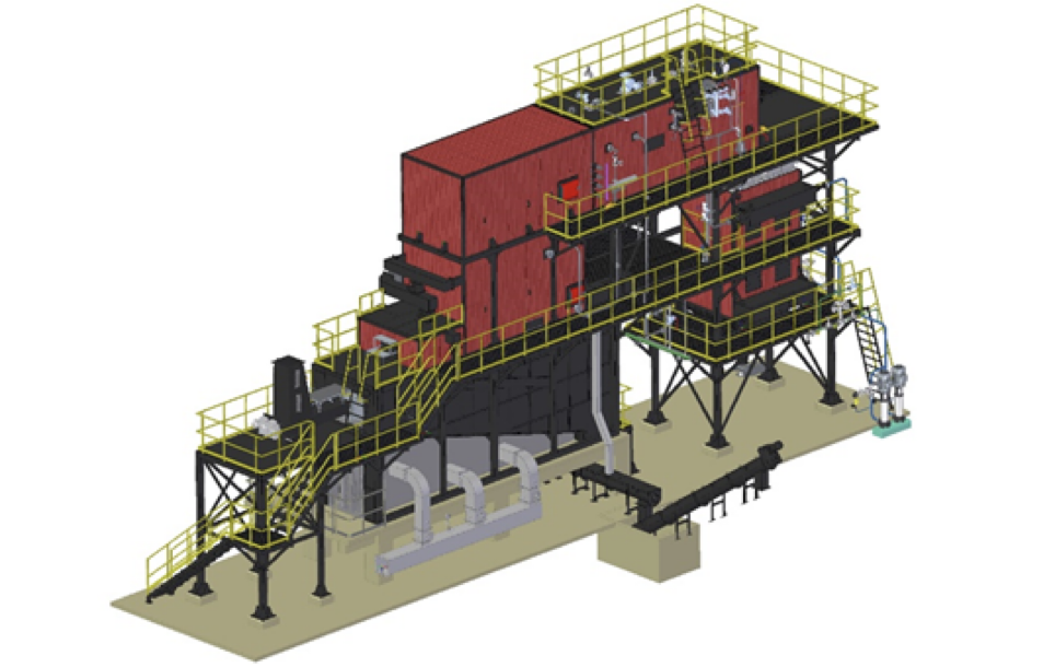
BDRG- Reciprocating grate Bi-drum boiler