Tata Power Company Limited
Introduction
Power generation, transmission and distribution supply chain helps in developing a nation with growing infrastructure and needs of the people. Massive amount of energy input is required for growth and development of infrastructure with reliable/round the clock uninterrupted supply of electricity. India is a nation with second largest population in the world having immense potential in the energy sector. With 130 billion plus population, the demand for power is increasing. The majority of power requirement is catered to by fossil fuels i.e. coal-based power stations constituting a total of 53.3% of power generation capacity. Coal is a non-renewable source of energy abundantly available in India. Indian coal which is mined for thermal power plants comes with moderate calorific value and high ash content. To address the high ash content and to take care of environment, many power stations have started using washed coal or blending the imported coal which basically comes from Indonesia or Australia. With the use of coal blending for power generation, changes are experienced in combustion which directly affects the boilers and slagging in the furnace and flue gas exit temperature.
The existence and development of adequate infrastructure is essential for the sustained growth of Indian economy. Electricity consumption is one of the important key indicators for measuring the development of nation.
In the world, India’s power sector is one of the most diversified sector. Sources of power generation vary from conventional sources such as coal, lignite, natural gas, oil, hydro and nuclear power to viable non-conventional sources such as wind, solar and agricultural and domestic waste.
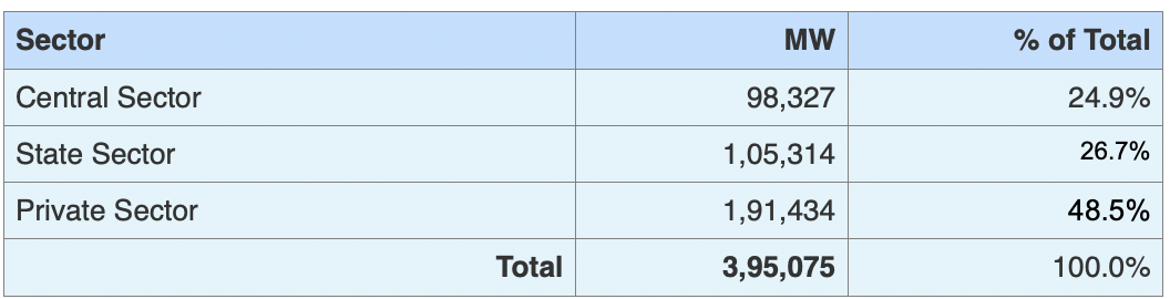
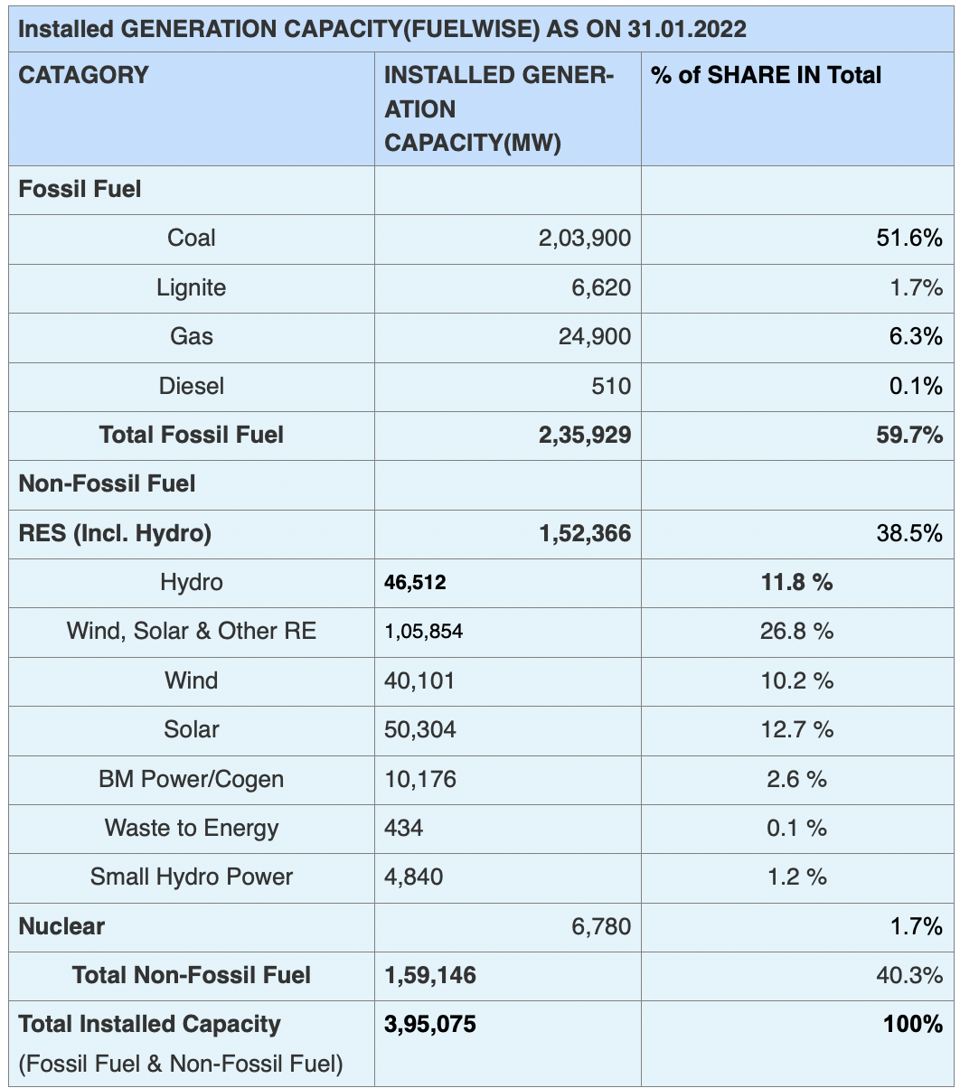
Total Installed Capacity (As on 31.01.2022)
(Source: Central Electricity Authority)
Capacity Sector Wise
Tata Power total thermal installed capacity:
Coastal Gujarat Power Limited (CGPL), Tata Power’s wholly-owned subsidiary, has implemented the 4150 MW UMPP near the port city of Mundra in Gujarat which meets nearly 3% of India’s power needs. This UMPP is India’s first 800 MW unit thermal power plant using supercritical technology, supplying to 5 states: Gujarat, Rajasthan, Maharashtra, Haryana and Punjab.
- Plant – CGPL- Coastal Gujarat Power Limited
- Location – Mundra, Gujrat
- Plant size – 4150 MW
- Type – Thermal
India’s first 4000 MW private power project near Mundra Port, Gujarat. India’s most energy efficient thermal plant using supercritical technology. This project will meet 2% of India’s power needs.
- Plant – Maithan
- Location – Dhanbad, Jharkhand
- Plant size – 1050 MW
- Type – Thermal
Maithon Power Limited (MPL), a joint venture with DVC, has implemented 1050 MW coal-based thermal power plant in Jharkhand. This project is India’s first 525 MW thermal power plant using subcritical technology, and the first PPP venture plant in the country. Benefitting close to 16 million consumers, apart from supplying cost competitive power to industry and agriculture, the project supplies power to New Delhi, Jharkhand, West Bengal and Kerala.
- Plant – Trombay
- Location – Trombay, Maharashtra
- Plant Size – 930 MW
- Type – Thermal
The Trombay Thermal Power Station, located in Mumbai, has an installed generation capacity of 930 MW. Providing power to majority consumers (bulk & retail) in Mumbai, the plant has a list of firsts to its credit. From the first 150 MW and 500 MW plant in India to setting up the unique islanding system which ensures uninterrupted power supply to Mumbai.
- Plant – Jojobera
- Location – Jojobera, Jharkhand
- Plant Size – 427.5 MW
- Type – Thermal
The Tata Power Company started its operations in the state of Jharkhand with the acquisition of 67.5 MW coal based captive power unit of Tata Steel in April 1997
To meet the increasing demand of Tata Steel, Tata Power decided to add more units in future. As a result of which five more 120MW units were set up in Jojobera in the year 2001, 2002, 2005, 2009 & 2011 respectively
- Plant – Prayagraj
- Location – Prayagraj, Allahabad
- Plant Size – 3 X 660 MW
- Type – Thermal
Prayagraj Power Generation Company Limited is a coal-based, 3*660MW, super critical thermal power plant located in Bara Tehsil in Allahabad District, Uttar Pradesh. The power plant is owned by Renascent Power, a subsidiary of the Tata Power.
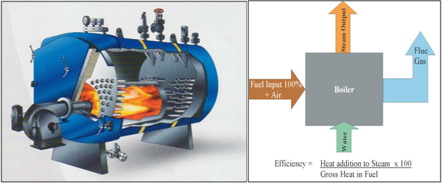
Overhauling of Boiler
It is evident from data that over 50% of energy requirements of India are met through thermal power plants using coal i.e., over 50% is being generated using steam generator or boiler. So it becomes very important that these boilers are well maintained and the mechanism that causes damages to these boilers, well understood and proper inspection techniques used to evaluate these damages and ensure that boilers are running defect free. In the periodic Overhauling process under the IBR Guidelines owners of these steam generators gets an opportunity to inspect the steam generators and carry out necessary works over these steam generator components to maintain their health, ensure safety and reliability. Periodic/annual overhauling of boilers helps in retrieving the desired efficiency of boilers which gets deteriorated due to deposition of ash in the pockets and heating surfaces. Also remnant life assessment of the components helps in deciding the replacement of high pressure and temperature components which helps in ensuring the safe operation of the boiler.
During overhauls, maintenance engineer gets an opportunity to:-
- Carry out annual health check up of boiler
- Resolve/attend to the defects of boiler.
- Cleaning heating surface area.
- Defect free run till next shut down
- Improving the efficiency of the boiler.
If overhauling is not done, it may lead to:-
- Unsafe operation of boiler
- Deterioration in performance/efficiency
- Increase in MTBF or frequent break-down of the equipment
- Rise in maintenance cost which further leads to rise in generation cost
- Loss of market share
- Loss of incentives associated with the generation availability
Overhauling of boiler is considered as critical process and following are the reasons
- Efficiency: Over a period of time boiler efficiency deteriorates due to formation of slag and ash deposition based on various types of coal firing. It gets cleaned during overhauls and helps in restoring the desired performance by better heat transfer through the cleaned surface area, thereby saving fuel.
- Uncertainty: When we consider about uncertainty it’s not the uncertainty in planning but the uncertainty regarding the defects appearing during inspection for which we are not prepared. For example a steam generator is under shutdown and inspection is being carried out the oxide scale thickness comes out to be very high in the superheater zone which may lead to breakdown in future. At this time a call is to be taken if the entire set of tubes having high oxide scale needs to be replaced. So this is just an example to understand the uncertainty which we may be faced with during inspection.
- Resource Management: Under the guidance and technical support, boiler repairers are obtaining qualifying certification from IBR for carrying out overhauls and repairs on boilers. The approved vendors can only work or execute the boiler overhauls. This helps in ensuring the quality-of-service providers/boiler repairers and gives confidence to the power plant/steam generating stations.
- Spares Quality & Availability: All boiler pressure part components are subjected to high pressure and temperature conditions. Hence it is very critical from reliability and safety point of view, the replaced/used component offer safe operation of boiler and with high reliability. IBR guidelines directs the boiler part manufacturers for manufacturing parts and components maintaining quality standards. Also, with experience of past history of failures, IBR gives necessary directions and guidelines to the manufactures for manufacturing which helps in improving quality and reliability of the components. All users of boilers should follow IBR guidelines in overhauling and RLAs so that the assessment of component health helps in deciding the procurement of the critical components which have high lead time. All components/spare parts use in boiler shall be certified before use to avoid quality issues.
- Standardisation of overhauling cycle time: Over a period of time power plant operators have benchmarked the processes of boiler overhauling, so that power plant is made available for support of grid requirement. However due to use of different coals like domestic or imported coal, the overhauling cycle time changes due to different slag formation properties and erosion of components which requires different time frames to address.
- Quality standards: Steam generator/boiler is one of the most critical equipment in a power station and for it to run efficiently and effectively it is very important to maintain the quality standards during entire overhauling process. Various quality standards issued by various governing bodies are to be strictly followed in order to maintain the health of boiler and maintain the efficiency of boiler.
- Organization Standards: When we are considering the organization standards its not about the organization who own the boiler/steam generator but its about the organization which will be carrying out the overhauling process for boiler/steam generator. Often it is observed that due to cost reduction the quality of the manpower which is being brought for overhauling the machinery affects overall boiler/steam generator quality and its health.
Overhauling Preparation:
Since overhauling is considered to be a critical process we need to prepare in advance keeping the following factors in the mind:
- Learnings from the previous shutdown
- Analysing the shortfall of spares and consumables required for the next shutdown
- Studying the metal temperature pattern of boiler metal tubes during running
- Analysing the soot blowing pattern
- Monitoring the pressure drop and FGET across the furnace.
- Thermography reports of the valves and any leakages through drain and glands of the valves.
- Any past tube leakages or any historical data of the steam generator which had led to break down
- Water chemistry monitoring throughout the boiler.
Overhauling is an important process for maintaining effectiveness and efficiency of the steam generators. Overhauling is a critical activity and there should be proper management process which oversees the entire process and ensure that overhauls are being completed on a timely basis with the desired results of efficiency and effectiveness.
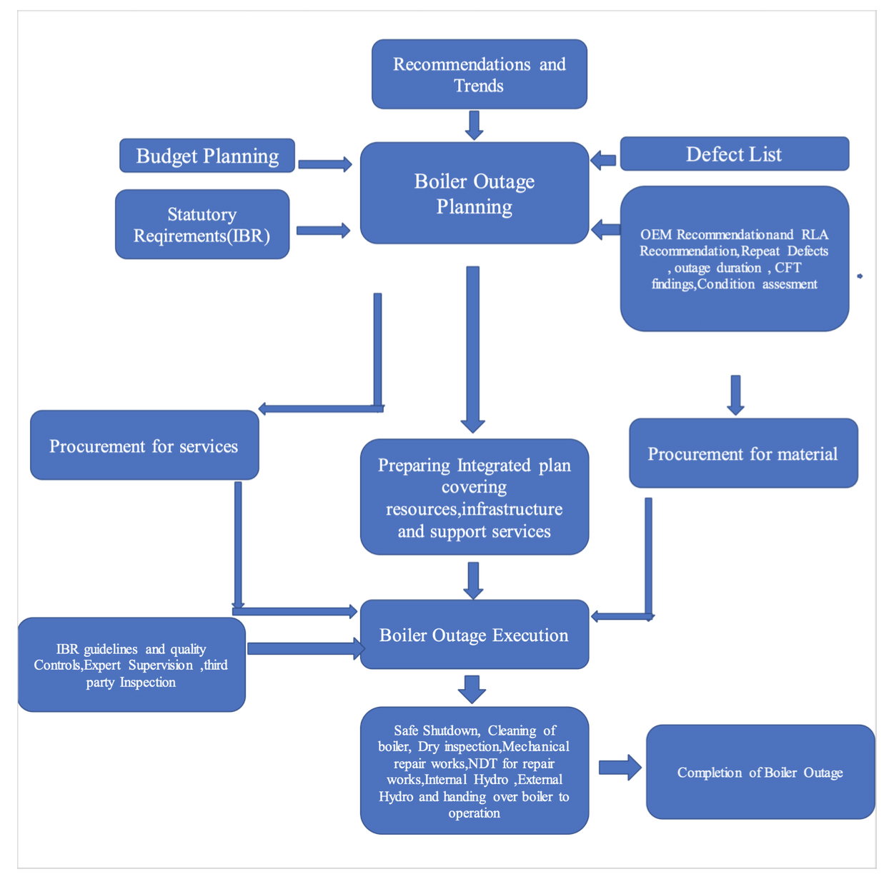
Tata Power also has different set of boilers at various locations and it also manages overhauling with a systematic and scientific approach. The flowchart below explains how the overhauls are managed –
Overhauling Management Process At Tata Power:
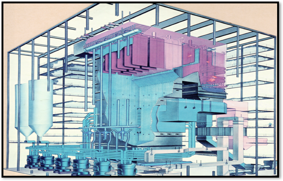
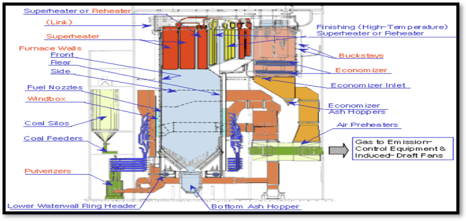
Different Zones in the Boiler:
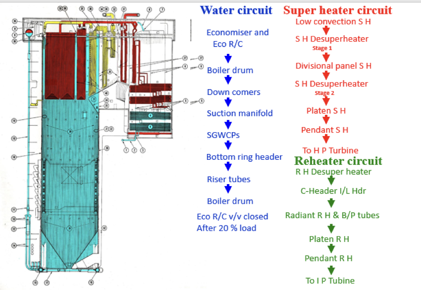
Water and Steam Circuit of a Boiler
Applicable codes and typical material of construction of boiler:
Following are different codes used for Boiler/Steam Generator
Design codes:
- Indian Boiler Regulation
- ASME BPVC Section 1- Rules for construction of Power Boilers
- ASME B31.1 -Power Piping
- EN12952-Water Tube Boiler and Auxiliary Installations
- AS 1228 Pressure Equipment Boiler
In-service assessment codes/guidelines
- Indian Boiler Regulations
- National Board Inspection Code- NB23
- ASME BPVC Sec VII- Recommended guidelines for care of Power Boilers
- ASME POM 101- Performance-related outage inspection
- ASME POM 102 – Operating walkdowns of power plants
- API 573- Inspection of fired boilers and heaters
- API 579/ASME FFS-1- Fitness for service
- EPRI- Electric Power Research Institute
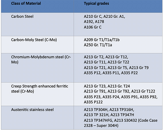
Material of Construction for Typical Boiler
Damage Mechanism in Boiler
With continuous operation and with time there are various damage mechanism which affect a boiler and it will further have potential of complete breakdown. Thus its very important for owner of boiler to identify these damage mechanisms and use proper RCA technique to analyse the solution for the damages which these damage mechanism are capable of affecting the boiler. The RCA (root cause analysis) is being done through the following steps:
- Identifying the mechanism
- Establishing the reason
- Planning the zones and extent of examination
- Correct selection of assessment technique
- Finally executing and evaluating
As per EPRI following damage mechanism prevail in various zones of the boiler:
| Creep | Fatigue | Corrosion | Internal Erosion/FAC | External Erosion/Corr’n | Thermal Mechanical Deform’n | |
| Waterwall Tubing(Ch2) | X | X | X | X | X | X |
| Superheater (SH) and Reheater (RH) Tubing (Ch 2) | X | X | X | X | X | |
| Economizer Tubing (Ch 2) | X | X | X | X | X | |
| Superheater Headers (Ch 3) | X | X | X | X | ||
| Reheater Headers (Ch3) | X | X | X | X | ||
| Steam and Lower Drums (Ch 4) | X | X | X | X | ||
| Waterwall Headers (Ch 4) | X | X | X | X | ||
| Downcomers (Ch 4) | X | X | X | X | ||
| Economizer Inlet Headers (Ch 5) | X | X | X | X | ||
| Main Steam Piping (Ch 6) | X | X | (2) | X | ||
| Hot Reheat Piping (Ch 6) | X | X | (2) | X | ||
| Superheater Crossover Piping (Ch 7) | (1) | X | X | X | ||
| Cold Reheat Piping (Ch 7) | X | X | X | X | ||
| Attemperators (Ch 8) | X | X | X | X | X |
Damage mechanism, root cause and area of impact.
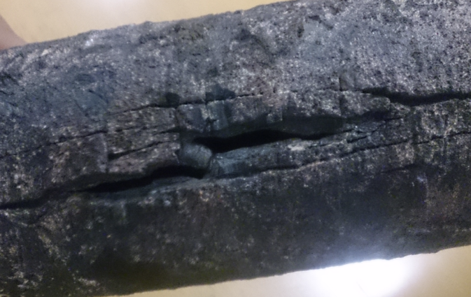
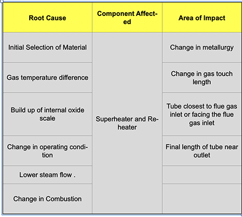
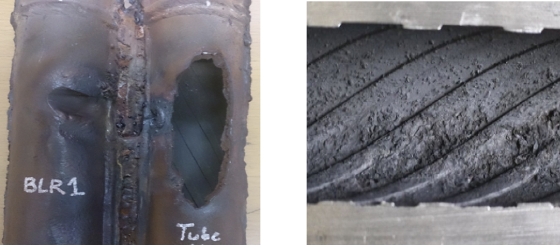
Creep/Long Term Overheating:
Creep is basically time dependent deformation at elevated temperature and under constant stress. Very common in superheater and reheater which run at elevated temperature.
Pictorial Representation of Creep Damage
In the following table we have tabulated the root cause, boiler component affected and area of impact.
Creep Range of Material:
Table 4.1- Temperature limit used to define the Creep Range
| Material | Temperature Limit |
| Carbon Steel {UTS < 414MPa (60 ksi)} | 343OC (650OF) |
| Carbon Steel {UTS < 414MPa (60 ksi)} | 371OC (700OF) |
| Carbon Steel – Graphitized | 371OC (700OF) |
| C-1/2Mo | 399OC (750OF) |
| 1-1/4Cr-1/2Mo – Normalized & Tempered | 427OC (800OF) |
| 1-1/4Cr-1/2Mo – Annealed | 427OC (800OF) |
| 2 -1/4Cr-1Mo – Normalized & Tempered | 427OC (800OF) |
| 2 -1/4Cr-1Mo – Annealed | 427OC (800OF) |
| 2 -1/4Cr-1Mo – Quenched & Tempered | 427OC (800OF) |
| 2 -1/4Cr-1Mo-V | 441OC (825OF) |
| 3Cr-1Mo-V | 441OC (825OF) |
| 5Cr-1/2Mo | 427OC (800OF) |
| 7Cr-1/2Mo | 427OC (800OF) |
| 9Cr-1Mo | 427OC (800OF) |
| 9Cr-1Mo-V | 454OC (850OF) |
| 12 Cr | 482OC (900OF) |
| AISI Type 304 & 304H | 510OC (950OF) |
| AISI Type 316 & 316H | 538OC (1000OF) |
| AISI Type 321 | 538OC (1000OF) |
| AISI Type 321H | 538OC (1000OF) |
| AISI Type 347 | 538OC (1000OF) |
| AISI Type 347H | 538OC (1000OF) |
| Alloy 800 | 565OC (1050OF) |
| Alloy 800H | 565OC (1050OF) |
| Alloy 800HT | 565OC (1050OF) |
| HK-40 | 549OC (1200OF) |
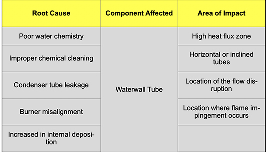
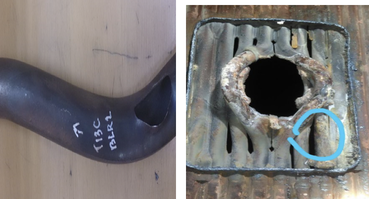
Hydrogen Damage:
Hydrogen damage is basically under deposit corrosion mechanism. Due to corrosion mechanism hydrogen gas is formed which diffuses into metal and combines with the carbon in the pearlite phase which further leads to brittle rupture of the metal. It usually is undetected till failure.
In the following table we have tabulated the root cause, boiler component affected and area of impact.:
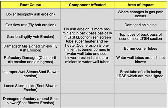
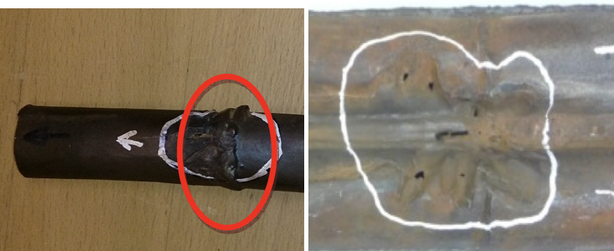
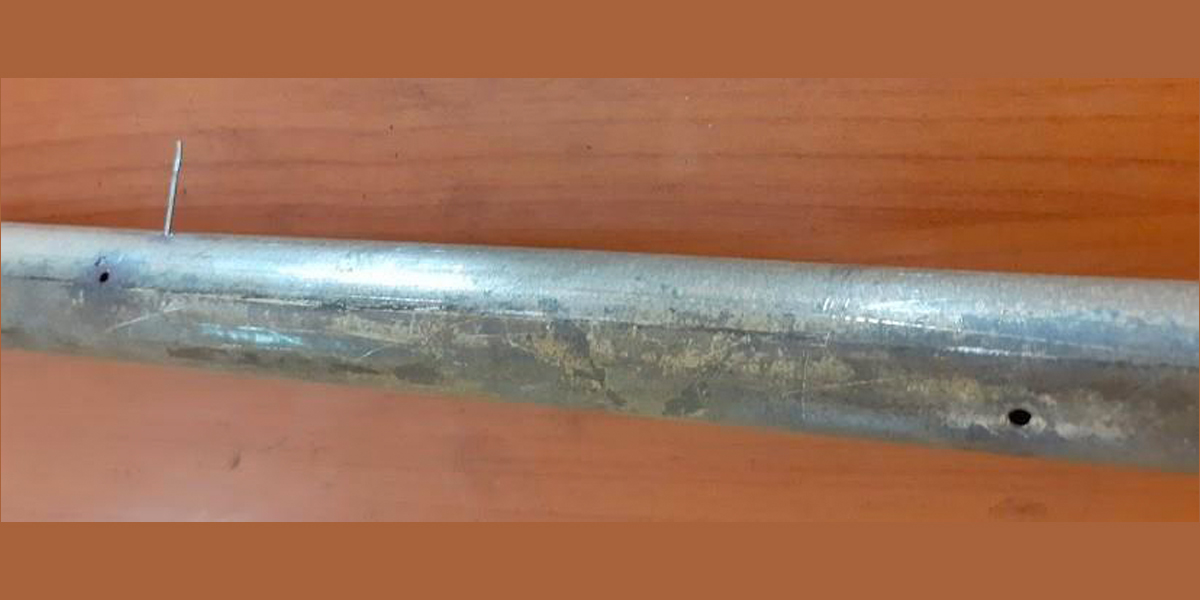
Erosion:
One more very prominent mechanism of failure in boiler tubes is erosion. Damages from erosion originate externally. Erosion is basically grouped as:
- Fly ash erosion
- Soot blower erosion
- Coal particle erosion
- Air ingress
In the following table we have tabulated the root cause, boiler component affected and area of impact.:
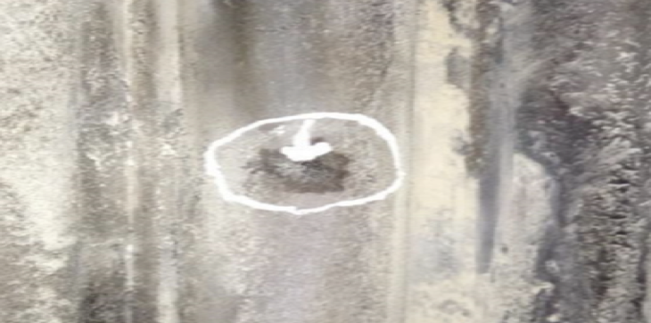
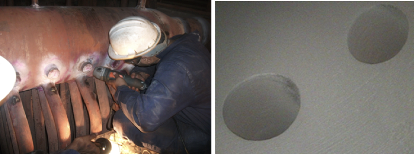
Weld Defects:
Weld defects are one of the major damage cause for break down of boiler. These type of failures often happens while boilers are in service and lead to break down of boiler/steam generator. The basic type of weld defects are lack of fusion, lack of penetration, slag, undercut, porosity, excess penetration. Process defects like that of pre-heat and post-weld heat treatment. These weld defects are usually undetected till the failure occurs.
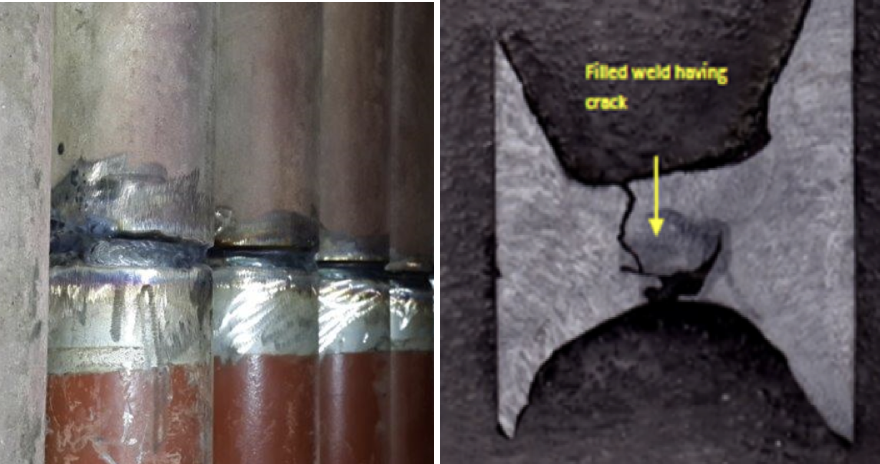
The welding defects typically will happen anywhere in the boiler where welding is being carried out. These defects are mainly caused by poor workmanship and not following the correct procedure.
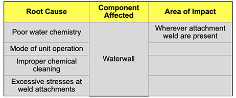
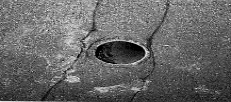
Corrosion Fatigue:
A typical failure which is a result of combined action of corrosion and cyclic stresses which results in the formation of multiple pits which further propagates due to further mechanical disruption and internal oxide layer formation.
Damage is generally seen in the tubes with attachment weld. Can happen inside or outside the furnace.
In the following table we have tabulated the root cause, boiler component affected and area of impact:
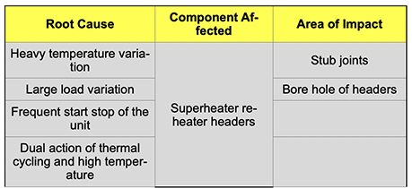
Creep fatigue/ Thermal fatigue:
Typical failure takes places in component with high wall thickness and working at high temperature. Common in high temperature headers. In this type of damage, life is significantly reduced due to creep and fatigue. The main location of damage are stub joint and bore holes of headers.
In service inspection:
Since we have understood the basic damage mechanism it is very important to perform in-service inspection to understand the health of the steam generator/boiler. While performing in-service inspection, it need to be know as to for what, and where to carry out the inspection, why at the particular location and which inspection technique is to be used and the right time to re-inspect. Correct answers to the above 5 queries will help with better results. We will classify various inspection techniques used for different component of boilers;
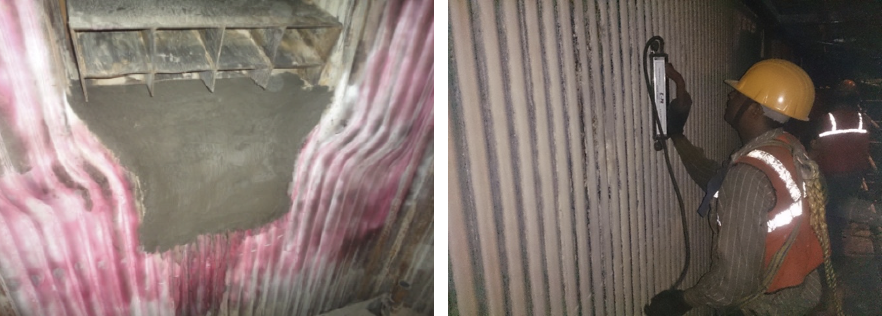
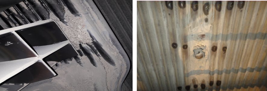
A. Water Wall:
Common damages that can be witnessed in water wall section are as follows:
- Erosion around wall blowers, coal burners
- Corrosion mechanisms, if any – hydrogen damage, acid phosphate corrosion, caustic gouging
- Air ingress from outside due to improper welding of fins
- Fly ash erosion
- Falling slag
- Fatigue mechanisms – corrosion fatigue, thermal fatigue
- Short term overheating
- Weld defects
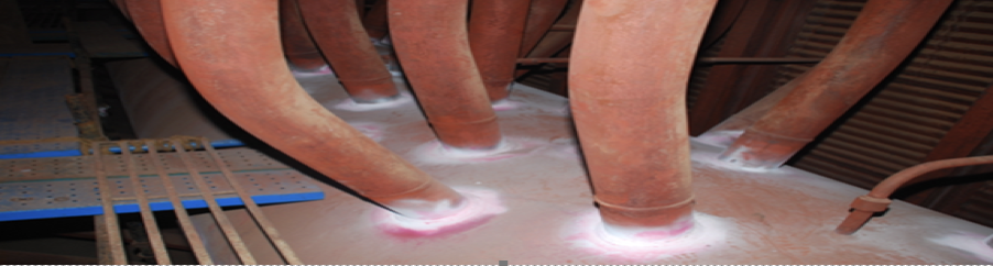
Inspection Techniques
- Visual examination around wall blowers, coal burners, peepholes, welded attachments, site weld joints
- Visual examination of tubes for signs of dents on tubes in bottom S-Panel, corrosion on waterwall where slag is formed
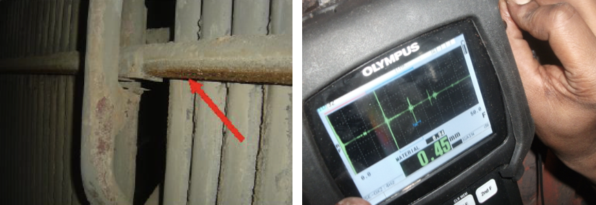
- Ultrasonic thickness measurement on tubes around wall blowers, coal burners, peepholes for erosion
- Dye penetrant examination on fins of tubes around burners, wall blowers, peepholes, if previous failures experienced due to weld shortcomings
- Ultrasonic thickness measurement on tubes at goose-neck area, at regular defined intervals in waterwall from S panel up to the roof
- LFET/RFET if any damages due to internal corrosion mechanism experienced in past or a scan needed for assessing a larger section for thickness loss due to erosion
- Specific plan and NDT in case of other known issues
B. Inspection of Economizer:
Common damages that can be seen in economizer are as follows:
- Fly ash erosion
- Flow accelerated erosion
- Acid dew point corrosion
- Weld defects
- Internal pitting
Inspection techniques used to inspect are:
- Visual examination for signs of missing/misaligned/damaged erosion shields, baffle boxes
- Visual examination for distorted /misaligned coils/tubes
- Visual examination for signs of any external corrosion/pitting , polished surfaces
- Ultrasonic thickness measurement on tubes at bends, top accessible bank, tubes out of place, tubes near headers
- LFET, if FAC is active esp. in tubing in economizer inlet header for assessing a larger section for thickness loss
- Radiography / PAUT in case known failures due to weld defects
C. Inspecting LTSH:
Common damages in LTSH are as follows:
- Thermal fatigue
- Corrosion fatigue
- Flow accelerated erosion – dual phase
Inspection Techniques :
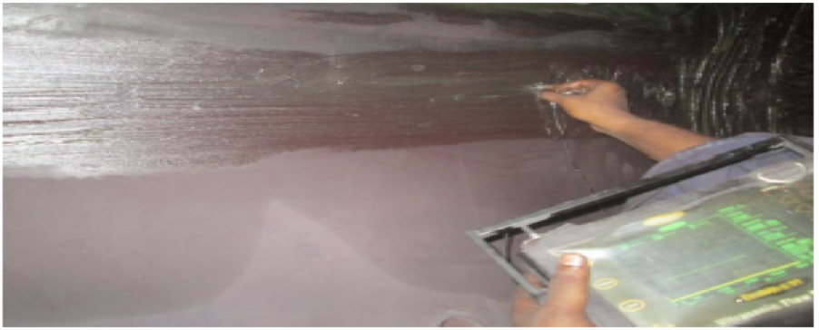
- Visual examination for general condition of drum and internals
- Ultrasonic thickness measurement for drum pressure boundary.
- Ultrasonic scan for seam welds
- Dye penetrant examination of stub welds, weld seams and drum internals
- WFMPI for examination of stub welds and other weld seams
- In-situ metallography on seam welds, HAZ and PM
- Hardness measurement generally on locations of in-situ metallography
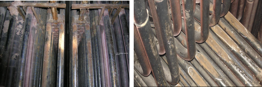
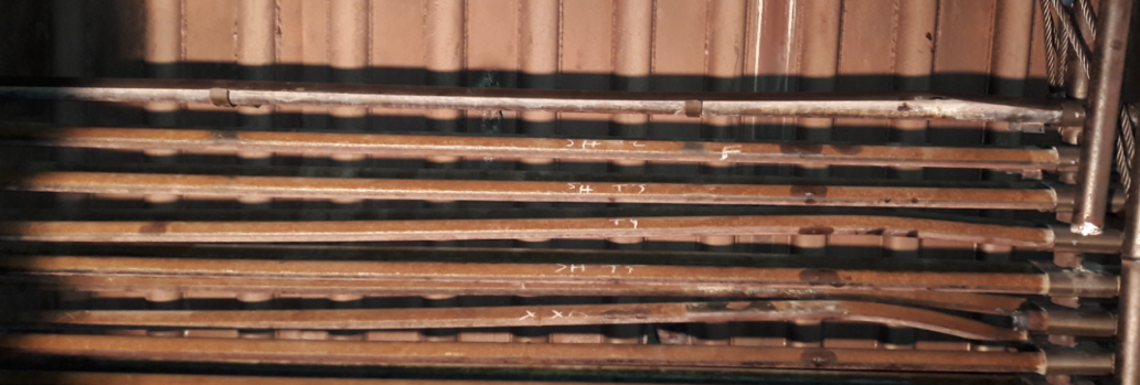
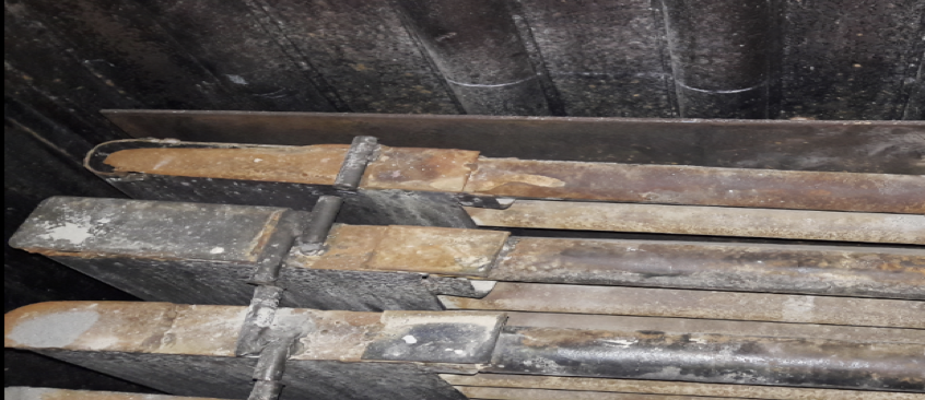
D. Inspecting superheater and reheater:
Common damages across reheater superheater are as follows:
- Fly ash erosion
- Fire side corrosion
- Creep
- Short term overheating
- Soot blower erosion
- DMW failures
- Weld defects
- Rubbing
Inspection Techniques:
- Visual examination for signs of missing/misaligned/damaged erosion shields, connectors, spacers, rubbing of tubes
- Visual examination for distorted /misaligned coils/tubes
- Visual examination for signs of polished surfaces/excessive scaling/blistering
- Ultrasonic thickness measurement on tubes at bends, tube surface facing flue gas, tubes out of place, locations along tube length
- Radiography/PAUT in case known failures due to weld defects and to assess joints operating in creep range + DMW
- Internal oxide scale thickness measurement
- Dye penetrant examination of cleats and attachments welded to tubes
- LFET for detecting internal blockage, if required
- PMI, if required
- Dimensional measurement, hardness checks
E. Inspection of high temperature headers:
Common damages in case of high temperature headers are:
- Creep
- Thermal Fatigue
- Creep – Fatigue
Inspection Techniques:
- Visual examination for general condition of headers, connecting stubs, missing/broken supports and hangers
- Boroscopic examination inside headers to assess condition of ligaments and check for any ligament cracking
- Dimensional measurement of headers
- Ultrasonic thickness measurement for header body.
- Ultrasonic scan of butt welds
- Dye penetrant examination of stub welds and other weld seams.
- WFMPI for examination of stub welds and other weld seams
- In-situ Metallography on seam welds, HAZ and PM to assess the creep damage
- Hardness measurement generally on locations of in-situ metallography
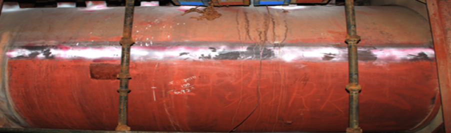
F. Inspection of boiler drum:
Common damages mechanism in the boiler drum are as follows:
- Thermal fatigue
- Corrosion fatigue
- Flow accelerated erosion – dual phase
Inspection Techniques:
- Visual examination for general condition of drum and internals
- Ultrasonic thickness measurement for drum pressure boundary
- Ultrasonic scan for seam welds
- Dye penetrant examination of stub welds, weld seams and drum internals
- WFMPI for examination of stub welds and other weld seams
- In-situ Metallography on seam welds, HAZ and PM
- Hardness measurement generally on locations of in-situ metallography
Best Practices:
Safety has been a very important attribute at Tata Power and same is being displayed even during the execution of the shutdown of the boiler. Tata Power ensures that all the technicians who will be working for overhauling are thoroughly certified through Tata Power Skill Development institute (TPSDI) with the required level of certifications. This certification is from Level 1 to Level 3 with Level 1 being basic certification, L2 being skilled based and L3 being exclusively for supervisors of the service provider. Also there is stringent permit system which is being followed at the site with permits being audited for HIRA and JSA.
Technology is one of the important tool which helps us maintain the equipment in healthy condition, retaining its efficiency and reliability. There have been various instances where we have successfully used the technology to ascertain the damages or to prevent further damage:
- Use of LFET in detecting FAC at economiser section
- Use of RFET for LTSH factory weld joint inspection
- Use of RFET and LFET for detecting hydrogen damage.
- Use of thermography to identify passing valves and carrying out insulation audit.
- Use of orbital cutting machines for cutting and edge preparation of high thickness headers
- Digitalization in thickness measurement with every tube in water wall section being mapped to its thickness, with each tube having a unique identity in the system.
- Carrying out air tightness test immediately after shutdown to find out the leakages and again doing after completion of shutdown to ensure all leaks are being attended.
Other than technology it is also the pro-active and preventive approach which we have been using to maintain reliability and efficiency of our boilers. We have ensured that all the components of boiler are covered under PM plans. Also proactively with the ageing we have been replacing various DMW joints at super-heater and re-heater sections.
Overall the safe operating processes, use of technology and digitalization and combination preventive and proactive approach, we have been able to maintain our steam generators both efficiently and high on reliability.
Conclusion:
Steam generators are critical equipment in a power station and to maintain them effectively, it is important to understand the damage mechanism and inspection technique to identify these mechanisms. With proper use of technology, safe operating process, IBR guidelines and mix of preventive and proactive approach the boilers can be maintained efficiently without compromising their effectiveness. This paper has tried to cover the various damage mechanisms and the inspection techniques required to identify these damage mechanisms and also the paper had tried to explain which damage mechanism is to be looked into which zone. Overall a clear understanding of damage mechanism and zone where its more likely to appear will be helping the owners of steam generator/boiler to keep the boiler efficient and reliable.
Abhishek Bapat, Lead Engineer-Mechanical Maintenance with Samad Mulla, Head-Mechanical Maintenance, Tata Power Company Limited, Trombay, Mumbai

Anil Vyas
June 9, 2022 at 5:58 amVery good article & useful for power plant engineers.