Boilers are installed in India either for power generation or for industrial use, burns coal, oil or agrowaste. Of the 100 million tons of coal consumed annually by various industries in the India, a significant part, about 55% is used by steam generating units. Similarly of the 25 million tons of oil consumed annually – mostly imported – about five million tons is used in boilers. India’s total coal reserve is estimated to be 83 billions tons, bulk of which is poor quality with high ash content.
The rising fuel cost forces attention to fuel management in industries. A minor deviation from the optimum efficiency of boiler plants will result in enormous loss of fuel. In a capital scarce country, fuel economy needs utmost attention in the industry. When there exist pragmatic vistas for achieving higher overall efficiency in boiler plants, it is the prime responsibility of engineers to focus their attention to minimise the fuel consumption and to conserve the scarce energy resources in the country. In the era of scarcity of fuel and paucity for foreign exchange, there is a crying need for conservation of fuel. Even a 1% decrease in boiler efficiency can squeeze an extra billion dollars out of the foreign exchange.
Not too long ago, the job of the boiler engineer and attendants responsible for boiler operation was to keep the combustion equipment operating safely with no visible smoke in the stack. The boiler room man and service technicians used their eyes and ears as their primary instruments, eyeballing the flame and listening to the operation of the equipment. Those were the days when fuel was inexpensive. Since 1973 fuel cost have gone up drastically with no end in sight.
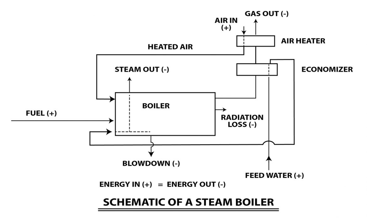
The details of the energy input (+) and energy output (-) in a boiler is shown in figure 1.
The areas where fuel can be saved in a boiler include
- The boiler proper
- Fuel
- Water
- Hot flue gases
- Steam
1) THE BOILER PROPER
a. Boiler Designs should be suitable for burning low grade fuel efficiently
In the case of power boilers, pulverised coal fired boilers offer the best choice for burning inferior grade of coals amongst the proven technologies. The drawback of the system of burning coal in the present context however is its need for oil supporting flame at low loads.
Conventionally, in case of industrial boiler, stoker fired units are used. The best known stoker designs may not be able to burn coal with ash content beyond 35%. Even where the ash content may be within the above specified limit, it is necessary that the coal is sized properly for efficient combustion, since the total fines in coal has a direct relation with combustion efficiency.
Conventionally, in case of industrial boiler, stoker fired units are used. The best known stoker designs may not be able to burn coal with ash content beyond 35%. Even where the ash content may be within the above specified limit, it is necessary that the coal is sized properly for efficient combustion, since the total fines in coal has a direct relation with combustion efficiency.
Under the present circumstances in our country neither the ash content nor the grading of coal is within the control of the user. As a result a considerable amount of energy is wasted in the form of unburnt carbon in ash and it become almost impossible to operate the boiler at its rated capacity. Industrial boiler users, therefore need to be given a specific consideration while allocating the coal supplies.
Selection of boiler furnace is based on the fuel available and their characteristics. Depending on the type of fuel one of the following type of furnaces is selected.
– Dumping Grate
– Traveling Grate
– Fluidised Bed
For bagasse as the only fuel, dumping grate is the best choice. For multi fuel firing, traveling grate is the right option. Dumping grate furnace is suitable for low ash content and low heat value fuels.
Depending on the fuel particle size and ash content, the speed of the grate can be varied. The combustion efficiency is also high due to proper spreading of fuel on the entire grate, thereby reducing the unburnt particle in ash.
The Fluidised Bed Combustion (FBC) boiler is best suited for devoted fuel having high ash content. Although the FBC technology gives higher boiler efficiency, the power consumption in auxiliaries is highest.
b. Selection and design of boiler auxiliaries to be optimised from the point of view of power consumption
Oversizing boiler auxiliaries and drives leads to insufficient operation of the equipment and the drives and wastage of electrical energy. By replacing oversized feed pumps, ID and FD fans by those of correct parameters, it is possible to save 4-5% electrical energy consumption.
c. Improvement of existing installations with a view to increase the efficiency
A survey must be conducted to identify existing boiler installation operating at low efficiency levels due to various reasons such as
– Inefficient combustion equipment
– Inadequate heat recovery equipment
– Inadequate/absence of insulations
– Absence of condensate recovery systems
– Absence of suitable water treatment resulting in a heavy blow downs etc
d. Variable frequency AC drives for boiler ID and FD. fans
In case of conventional AC drives of ID/FD fans, motor has to be run on constant input power irrespective of the damper percentage opening(i.e. Quantity of airflow is controlled by damper). Controlling motor speed by varying frequency can control this air.
By applying affinity law,
HP2/HP1 = (Q2/Q1)2
Where
HP = Horse power, Q = Air flow, N = Fan speed
Also
(Q2 / Q1) = (N2 / N1)
For example, If ID fan motor rating is 270 HP (HP1) for 100% (Q1) flow. Now by changing the speed, suppose flow has been reduced to 80%, then new HP (HP2) will be
i.e HP2 = 270 x (80 / 100)3 = 138 HP
Thus, almost 50% power can be saved.
In addition to energy conservation, these drives have variable frequency control which accelerates the motor with starting current of 150% as against 350-450% in case of conventional drives. This reduces high KVA demand during starting and increases the motor life. In addition, programmable high starting increases motor life. In addition, programmable high starting torque can be achieved at low load due to auto voltage boosting facility.
e. Avoid over sizing the boiler
When an oversized boiler is installed in a plant, it quickly satisfies the steam demand of the plant. When the steam demand of the plant is satisfied, the boiler has to be shut down until the steam demand comes from the plant once again. This results in short cycling of the the boiler
Most boilers operate on cross limiting control system i.e. where the air flow increases before the fuel flow increases and air flow decreases after the fuel flow decreases. Thus during the switch off-on mode of the boiler, heat is carried away by the air to the stack, reducing the overall efficiency of the boiler.
Thus the frequent on and off of the boiler causes heat in the combustion chamber to be carried away by air purging. This results in greater stack loss and reduction in overall efficiency of the boiler. Hence, over sizing of boiler must be avoided.
f. Opting shell type boiler over coil type boiler leads to availability of good quality steam and reduces process steam requirement
The running cost of shell type boiler is 20 to 30% less than that of coil type boiler. This is because the dryness fraction of steam generated from the coil type boiler is low compared to that of shell type boiler. The dryness fraction represents the percentage of steam i.e. dry and percentage of moisture in a given volume. A low dryness fraction indicates steam contains more moisture.
Consider the process requirement of 200,000 kcal / hour
Working pressure of steam : P = 3.0KSCG
Saturation Temperature of steam : T = 145.06oC
Latent heat of steel : L = 508.25 kcal/kg
Table 1
| Parameter | Coil Type Boiler | Shell Type Boiler |
| Dryness fraction | 0.8 | 0.98 |
| Steam required to meet demand | H = h + XL (Sat steam) H = h + L + CP (T sup – T sat) (superheated steam) H = h + XL (Sat steam) 552 = 145.06 + 0.8 x 508.25 200000= X x (552 – 145) X = 490 | H = h + XL (Sat steam) H = h + L + CP (T sup – T sat) (superheated steam) H = h + XL (Sat steam) 643 = 145.06 + 0.98 x 508.25 200000= X x (643 – 145) X = 392 |
Thus with a coil type boiler 25% more steam will be required over a shell type boiler.
g. With coil type boiler condensate cannot be recovered, condensate contains 20% of the energy
Condensate contains 20% of energy. In a coil type boiler positive displacement pump is used. Because of the temperature limitation of the positive displacement pump, the condensate cannot be pumped back into the coil type boiler by positive displacement pump. Therefore the condensate which contains 20% heat energy cannot be used in coil type boiler. Due to this the fuel loss would be 9 to 10% of the total fuel consumed. Thus the boiler should be supplied with fresh water equal to the steam demand. This fresh water used requires treatment which associates with treatment cost.
2) FUEL
a. Avoid the use of oil wherever possible
Considering the fact that India has fairly big coal reserves compared to oil and also because of the fact that oil has to be imported, it makes sense to design boilers to fire coal or agro waste. Unless the consumption of oil is curtailed the requirement of foreign exchange is bound to increase at an alarming rate.
While coal fired boilers can be converted to fire oil easily, conversion of oil to coal firing is considered difficult. Modifications that are necessary to convert an oil fired boiler are too elaborate and cumbersome and thus, expensive. Even where conversion is feasible, it may result in derating of the boiler. Considering energy saving, it may still be worthwhile exploring the possibility of converting the large oil fired boilers to burn low grade coal.
Since we have a long way to go to meet our ever increasing power requirement, it is of vital importance to exercise caution and avoid the use of oil fuel for all future installations. In order to have effective control, it may be worthwhile to evolve suitable procedures for regulating the selection of fuel for new boiler installations.
In the case of oil-fired boilers that are due for replacement, industries must be persuaded to switch over to coal fired boiler or agro waste fired boilers wherever possible. In the case of other oil-fired installations, the possibilities of replacing existing oil burners with more efficient ones may be examined.
b. Avoid the use of oil for stabilisation
The inherent requirement of pulverized units is the need for start up and flame stabilisation at low loads, which at present is met by burning oil. The possibilities of using alternative methods/fuels for flame stabilisation viz., use of producer gas, or high energy should be considered seriously.
In bagasse fired boiler, during stoppage of crushing, the boiler will not get bagasse feed from the mill house. In such situation the tendency of the boiler operators is to use oil to maintain the required steam pressure. The usage of oil in such case can be avoided by feeding sufficient quantity of bagasse through the return bagasse conveyor using mechanical feeding devices.
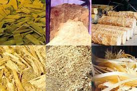
c. Utilisation of non-conventional fuels
Considerable potential exists in the country for utilisation of materials such as municipal refuse, paddy husk, coffee husk, saw dust, bark, wood waste etc., as fuels in boilers.
All these, non-fossil fuels, until now, satisfies only the social need of majority of the people without contributing to the national economic progress. Most of the high quality resources used for steam/power generation such as coal, oil and gas etc. are limited. But the consumption of energy is increasing rapidly while the natural resources are proportionately depleting. To resolve this, every calorie of thermal energy remaining in the non-fossil fuel has to be recovered and utilised, thereby extending the availability of high quality fuel for a longer period of time. Many technologies have been tried in the initial stage and finally it has been found out that the fluidised bed technology is the only effective technology that can serve and deliver the derived results by burning low grade fuels.
In the conventional stoker type boiler, when agricultural waste such as paddy husk, bamboo dust, bagasse, wood chips are to be burnt, a separate furnace is required from which the flue gas is led into the boiler. With FBC (fluidised bed consumption) boilers, there is no need for a separate furnace. This waste can effectively combusted in FBC boiler without the use of supplementary fuel. Hence, it is one of the advantages of fluidised bed combusters, that they can be used for combustion of any kind of fuel to produce heat or as incinerator of combustible materials or for heat recovery proposal. Depending on the fuel characteristics, specific combuster design is required to burn agro waste either independently or in combination of either high or low quality fuel like coal lignite etc. in an effective way.
The advantages of fludised bed combustion boilers are
– Ability to burn low-grade fuels
– High thermal efficiency
– Ability to burn fines
– Flexibility to burn agro waste fuel
– Less excess air higher Co2 in flue gas
d. Maintaining Proper Combustion with Derived Air Ratio
We need 14.1Kg of air for every Kg of fuel oil consumption. This is the minimum air that would be theoretically needed if mixing of fuel and air by the burner is to be perfect. Since perfect mixing can never be achieved, a certain amount of excess air is needed to complete combustion and ensure the release of entire heat contained in the fuel oil. If air is in great excess, additional heat would be lost in heating the surplus air to the chimney temperature. If the air is less than what is required for complete combustion were allowed to enter, then this would result in incomplete combustion. For proper combustion, optimally excess air (normally 20%) and carbon dioxide between 12.5% – 13.5% (or oxygen between 3% to 4%) level has to be maintained which would consume the least fuel and correspondingly maximise the efficiency of the boiler. 5-10% fuel savings are possible by controlling the excess air. 100% excess air reduces boiler efficiency by 5%.
Calorific value of carbon monoxide is 2430 kcal/kg and that of carbon-dioxide is 8084 kcal/kg and hence maintaining high carbon-dioxide at the chimney base cannot be over emphasised.
e. Prevent leaping out of flame outside the furnace and other opening
Align Burner (S) properly. Adjust flame length, if flame leaps out of flues, fire hole and furnace doors and other openings it will result in direct loss of fuel.
Keep the furnace door closed, close all openings including inspection holes closed. Failing which ingress of air will takes place and infiltrated air cools the furnace down and thus increases fuel consumption. As a thumb rule an increase of air leakage by 5% leads to increase in the excess air level and also loss of boiler plant efficiency by 0.5-1%. A slight positive pressure will prevent air infiltration. Exfiltration of dust and fumes into the boiler room makes good housekeeping an impossible task.
f. Optimise Fuel Atomization Pressure
Adjust the fuel pressure according to the nozzle operating instruction. Fuel atomization is a function of
i) Fuel Pressure
ii) Fuel Viscosity
iii) Primary Air or Steam (which ever is used) and
iv) Nozzle design
Operating the burner at higher or lower pressure will decrease combustion efficiency. 1% fuel can be saved with correct fuel atomization pressure.
g. Optimise Fuel Viscosity
Atomise the fuel at right viscosity. Too high or too low a viscosity will yield poor atomisation or poor efficiency. The boiler nozzles are designed to facilitate correct blending of fuel and air so that combustion efficiency will be optimised. If the fuel is too viscous or too thin, the air fuel blend will suffer, resulting in lowering combustion efficiency. By optimising the fuel temperature, a saving of 5% in fuel consumption can be achieved.
3) WATER
a. Fuel loss due to scale and deposits on the water side
If scale or sludge is deposited on the waterside of the heating surface, heat transfer in the boiler is impeded and circulation is hampered. Sludge can be removed from the boiler by blowing down. Due to accumulation of scale, the heat transfer is affected, the temperature of the pressure part rises and the metal yields due to loss of mechanical properties, the pressure part bulges and sometime ruptures.
It is estimated that 1mm thick scale on waterside of the boiler increases the fuel consumption by 5% – 8%.
b. Fuel loss due to boiler blow down
The extent of blow down depends on the dissolved solids in the boiler water. There are two types of blow down.
- The intermittent blow down – Mud blow down designed to remove heavy sludge at the bottom of the boiler.
- Continuous blow down – Skimming blow down designed to remove solids dissolved in the water.
A continuous blow down system is a better arrangement than intermittent blow down for economically maintaining concentration limits. In such a system a small quantity of water is continuously blown down and the quantity easily adjusted depending upon the load and chemical analysis.
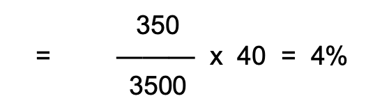
To maintain boiler water concentration within specified upper limit of boiler water TDS blow down is resorted to. The following formula gives the quantity of blow down required.
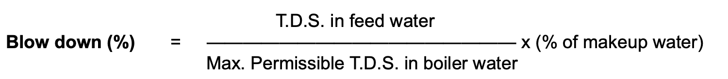
If maximum permissible limit of TDS in a boiler is about 3500 ppm and percentage of makeup water is 40 and if TDS in feed water is 350 ppm then the percentage of blow down
If the boiler evaporation is 5500 Kg/Hr, then the required blow down rate
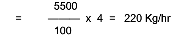
Table 2
PERCENT OF BLOWDOWN VS. PERCENT EFFICIENCY LOST
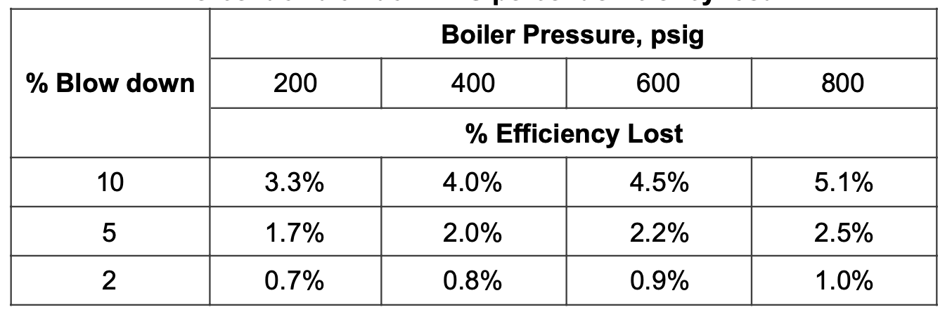
For instance in reducing the percentage of blow down from 10% to 5%. There is a 1.7% gain in boiler efficiency for a 200-psig boiler. Regular checks of total dissolved solids, alkalinity etc., in the blow down and feed water will determine how much blow down is really necessary.
c. Maintaining high TDS levels in the boiler drum result in water carryover and foaming. This leads to wet steam and lower heat transfer efficiencies to the process.
As the boiler generates steam, the impurities in the boiler water will not boil off with the steam. As the generation of steam continues in the boiler, the concentration of impurities will increase in the boiler drum. As the concentration of impurities increases, the steam bubbles rising from the bottom of steam drum tends to become more stable and fail to burst as they reach the water surface of the boiler.
There comes a point where substantial part of the steam space in the boiler is filled with bubbles and thus foam is formed on the surface of the boiler water. This foam is carried away along with steam. Thereby the dryness fraction of steam decreases. Consequently the fuel consumption will increase.
d. Boiler operation parameters should be monitored continuously to correct operation
The cost of buying a new boiler is small, when compared to the amount of money spent in operating the boiler year on year. This is a known fact and known is that, this amount of money spent in operating the boiler is governed by the boiler efficiency. Although the boiler efficiency is an important parameter in the specification when purchasing a new boiler, little attention is paid to this when the boiler is steaming. Boiler’s by themselves do not operate efficiently, but need to be operated efficiently in a manner that they delivery best efficiency. Therefore the first parameter to be measured is steam fuel ratio. Steam fuel ratio is total steam generated to the total fuel consumed. Therefore this parameter should be regularly monitored. A minor decrease in steam fuel ratio from 13.5% to 13.25% translates into a 1.85% variation in fuel consumption.
4) HOT FLUE GASES
a. Recovery of waste heat
It would appear that there are many cases particularly in the chemical and metallurgical industry where considerable amount of heat energy is let out to the atmosphere un- utilised. An industry wise survey should be conducted to identify such areas to assess the feasibility of recovering heat energy by introducing suitable boiler.
The source of waste heat in process industries are classified as under
SOURCE OF WASTE HEAT IN PROCESS INDUSTRIES
High Temperature Source | Low Temperature Source | ||
| 1 | D.G. Set Exhaust | 1 | Steam Boiler Exhaust |
| 2 | Gas Turbine Exhaust | 2 | D.G. Set Jacket Water Heat |
| 3 | Furnace Exhaust | 3 | Condensate from Process |
| 4 | Incinerator Exhaust | 4 | Condensing Vapour from Reactor/ Distillation Column |
| 5 | Thermic Fluid Heater Flue Gas Exhaust | 5 | Dryer Exhaust |
| 6 | Hot Air Generator Flue Gas Exhaust | 6 | Boiler Blow Down |
Many industrial/installations exhaust flue gases at fairly high temperatures and there are tabulated below
Table 3
| Sl. No. | Waste Heat Source | Source Temperature |
| 1 | Gas Turbine Exhaust | 500 – 600 |
| 2 | Diesel Engine Exhaust | 250 – 450 |
| 3 | Flue Gas from Cement Kiln (dry process) | 350 – 370 |
| 4 | Reformed gas, synthesis gas, converted gas etc., in fertilizer plants | 900 – 1000 |
| 5 | Flue gases in glass Industries | 900 – 1000 |
| 6 | Flue gases from various furnace in steel Industries | 400 – 900 |
A typical 20MW gas turbine works on open cycle exhaust 108Kg/s of flue gas at 512deg C.
By installing an unfired waste heat recovery system superheated steam at 23 ata 405 deg C can be generated by the waste heat boiler to ultimately produce 10MW of electric power by the steam turbine.
In a typical 3000TPD cement plant,110Kg/S of flue gases are available at 370deg C (approximately) from the rotary kiln. A waste heat power plant can be suitably designed to recover heat from the above waste gases to generate 28T/hr of steam at 12.5 ata and 305deg C and to ultimately produce an electrical power of 4.2 MW
Normally, diesel engine exhaust heat recovery gives raises to only low-pressure steam and as such can be used only for process requirement. If the diesel engine runs on limited hours the same is not viable.
b. Fuel loss due to high stack temperature
To estimate combustion efficiency two parameters must be known i.e., stack temperature and percentage of carbon-dioxide. The net stack temperature is obtained by subtracting the ambient temperature from flue gas temperature.
A high net stack temperature indicates that, heat is being wasted to atmosphere without being properly utilised in the boiler. Good practice dictates that the stack temperature be as low as possible without causing cold-end corrosion (Dew point corrosion). Cold end corrosion is generally caused by the formation of sulphuric acid (H2SO4) when sulphur tri-oxide (SO3), which is generated during the combustion of fuel, comes in contact with water vapour. Sulphur in fuel burns to SO2. In the presence of large amount of excess of air, some of this will be converted into SO3. Usually 1-3% of which combines with water vapour to form sulphuric acid. If the temperature of air heater, air ducts and stack falls below the acid dew point, the sulphuric acid will condense on metal surface.
This can be countered by
– Injecting ammonia into gas stream
– Neutralising SO3 of flue gas by ammonia
High temperature corrosion is due to the presence of vanadium and sodium salts in the fuel. During combustion they get vapourised and deposit on relatively cooler surfaces of super heater with skin temperature around 550-600deg C. The more volatile sodium compound adheres first to the surface and produces a rise in the temperature of sticky surface conditions. The vapours of vanadium salts help build up these deposits thus hindering the passage of heat from hot gases to the steam inside the super heater.
High stack temperature may be due to following reasons:-
a. Short circuit of flue gases due to fallen damaged baffles in the flue path
b. Impairment of heat transfer due to
i) Scale deposit on waterside
ii) Soot deposit on fireside of the heat transfer surface
c. Insufficient heat transfer area provided due to faulty design.
d. Insufficient of heat transfer area due to removal of part of part of heating surface due to damage.
17deg C rise in stack temperature means 1% rise in fuel cost. In any case the stack temperature must be 30deg C and 85deg C higher than saturated steam temperature of oil and coal fired boilers respectively corresponding to the specified working pressure.
c. Preheating of Air
Preheating of secondary air in the case of solid fuels and the entire air in the case of other fuels confers many benefits. Even in the case of solid fuels the entire air is heated in pulverised fuel firing:
a. 1% gains in thermal efficiency for every 30 deg F fall in flue gas exit temperature by using it to preheat air;
b. Preheated air gives higher flame temperatures and hence increased heat transmission through radiation;
c. Easier to burn lower grade fuels;
d. In the case of mechanical stoker, the preheat of air should not be too high as to increase the flame temperature to such a limit as to destroy the grate.
Table 4
| Grate | Limiting Secondary Air Preheat Temperature |
| Chain grate stoker | 300 deg F |
| Retort stoker | 400 deg F |
| Pulversied fuel firing | 600 deg F |
d. Fuel Loss Due to Soot Deposit on Fire Side
External cleanliness of the boiler, super heater economiser, reheaters and Air heaters has direct bearing on.
i. Efficiency
ii. Generation capacity
iii. Pressure maintenance and
iv. Draft loss
The frequency of cleaning depends upon
i) Quality of fuel
ii) Exhaust gas temperature
iii) Load condition
iv) Steam temperature and pressure
v) Disposition of the equipment
It may be noted that 1/8″ of soot on a heating surface has the insulating effect of a 5/8″ layer of asbestos.
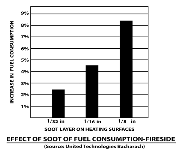
Figures shows one-eighth inch soot deposit on fireside could decrease efficiency by 9% and increase fuel consumption by 2.5%. Use additives with fuel to minimise soot deposits or use soot blowers if available.
5) STEAM
a. Fuel loss due to steam leakage
If due attention is not paid to prevent steam leakages, it can be a major factor of fuel loss. It has been estimated that a 3mm diameter hole on a pipeline carrying steam at pressure of 7KSCG, would waste 32.65 KL of fuel oil per year. Steam leaks on high- pressure steam line are prohibitively costlier than on low-pressure steam line. In many of the industries this is a neglected area
Any steam leakage must be quickly attended to. In fact, the plant should consider a regular surveillance programme for identifying leak in pipelines, valves, flanges and joints as soon as they occur. To minimise steam leakage from flange joints it may be worthwhile to have weld joints instead of flange joints.
Table 5
Steam Losses through Piping Leaks
| Hole size in inch | Steam wasted in Ib/month |
| ½ | 835,000 |
| 7/16 | 636,000 |
| 3/8 | 470,000 |
| 5/16 | 325,000 |
| ¼ | 210,000 |
| 3/16 | 116,600 |
| 1/8 | 53,300 |
Table 6
Steam Losses at Different Pressures
| Steam System Pressure, | Loss rate (Ib/hr for hole size indicated) | ||||
| psig | 1/16 in | 1/8 in. | 1/4 in | 1/2 in | 1 in |
| 1000 | 18.00 | 73.00 | 290.00 | 1161.00 | 4645.00 |
| 200 | 34.00 | 137.00 | 543.00 | 2171.00 | — |
| 400 | 66.00 | 262.00 | 1048.00 | — | — |
| 850 | 137.00 | 546.00 | — | — | — |
b. Fuel loss due to high radiation losses
Bare steam pipelines, flanges and hot processing equipment give up heat to the atmosphere by radiation. It has been estimated that a bare steam pipe of size 150mm dia and 100 meters in length carrying saturated steam at 8 KSCG, could waste 25KL of furnace oil in one year. Prevention of heat leakages by judicious application of thermal insulation is the simplest method of achieving substantial economy in energy consumption.
Thermal insulation serves several functions such as
- Saving of Energy
- Fire Protection
- Conservation of products
- Control of temperature
- Increased Production
- Better Working Conditions
Materials vary widely in heat conducting properties. This is expressed by the term thermal conductivity. Thermal conductivity is the amount of heat transferred in unit time through a unit area of unit thickness with unit temperature across the face. Thermal conductivity of a given material usually increases with rise in temperature.
Lagging Flanges
Some engineers generally commit the error of leaving the flanges and valves unlagged while insulating the piping systems. In fact, some insulating contractors recommend that
flanges should not be lagged if operating temperatures are less than 200oC. Such recommendations portray lack of knowledge on the economy of insulation. Often, flanges are left bare, due to the fear that leaks may go undetected and that leakages may corrode the flange bolts.
There are several reasons to dispel this practice. First of all, if the moulded box lagging is used for flanges, a 75mm length of a 6mm pipe may be inserted into the bottom of the box to give an early warning of any leak. Secondly, a really bad leak will soon make itself known. Third, lagging the flanges is one of the best ways of stopping leaks.
Bare flanges on hot lagged pipes introduce temperature stresses at the flanges, which may be the cause of leaks. The heat loss from uninsulated flanges and valves is equal to approximately that from a 0.5 meter and a 1 meter bare piping respectively. The heat loss from an uninsulated flange may equal that from several meters of insulated piping and a piping system with bare loss compared to that of a fully insulated system. The effect of retaining uninsulated piping, flanges and valves can be seen from table below.
Table 7
Equivalent fuel loss from uninsulated surface
| Liters of furnace oil / annum / meter length | |||||
| Temperature (oC) | Pipe dia (25 mm) | Pipe dia (50 mm) | Pipe dia (75 mm) | Pipe dia (100 mm) | Pipe dia (150 mm) |
| 50 | 15 | 28 | 40 | 50 | 68 |
| 100 | 74 | 133 | 190 | 250 | 360 |
| 150 | 160 | 288 | 410 | 472 | 680 |
| 200 | 248 | 426 | 620 | 786 | 1136 |
| 250 | 340 | 628 | 916 | 1182 | 1713 |
| 300 | 482 | 895 | 1290 | 1628 | 2428 |
Assumptions
a) Ambient Temperature 30oC for still air
b) Hr of operation. 8100
c) Pipe external surface Mild Steel
Table 8
| Temperature (oC) | Surface covered with aluminum sheet (Liters / annum) | Surface covered with galvanized mild steel (Liters / annum) |
| 50 | 80 | 113 |
| 100 | 366 | 520 |
| 150 | 708 | 1050 |
| 200 | 1118 | 1757 |
| 250 | 1588 | 2660 |
| 300 | 2116 | 4194 |
Calculations based on
6000 hours/year Average ambient: 30oC
Still air condition:
Boiler efficiency: 81.8%
Gross Calorific Value:10,300 kcal/kg
Sp. gravity of oil: 0.95
Insulation of boilers
Boilers for power plants and industrial applications have membrane walls or skin casings on which thermal insulation is applied directly to the walls, without any need for refractory protective materials. Maximum temperatures to which the boiler wall insulation is subjected are saturated steam conditions, which would not normally exceed 350oC. Insulation of large boiler walls is usually achieved by the application of mineral fibre slabs, applied in two layers, secured to studs and finished with either galvanised mild steel or aluminium. The chosen insulation should be sufficiently resilient to accommodate relative thermal expansion between boiler wall and outer metal finish.
Insulation of gas flues
Gas flues are insulated to maintain the required gas temperature in the chimney and to prevent corrosion by maintaining the temperature of flue walls above the dew point of gases. The vertical sides and bottom of the flue may be insulated with low density insulation, supported on studs and reinforcing mesh, but the top of the flue which is liable to foot traffic should be insulated with material of sufficient resistance to compression, in order to withstand imposed loads. The tops are normally insulated with calcium silicate or high-density mineral wool. Expansion joints in gas flues should be insulated to prevent acid deposition.
c. Fuel loss due to non-Recovery of condensate from auxiliary steam system
Condensate is formed when steam condenses, accidentally – inside a steam pipe – or purposely – inside heating surface. The steam condenses after giving off its latent heat in the heating coil or the jacket of the process equipment. A sizeable portion (about 25%) of the total heat in the steam leaves the process equipment as hot water.
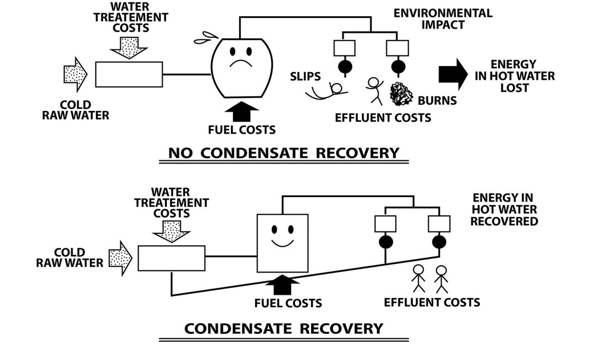
With a good percentage of the condensate returning to the boiler house:
I) Fuel requirement of the boiler will be reduced. For every 6 deg C rise in the feed water temperature there will be approximately 1% saving of the fuel in the boiler.
ii) The condensate is almost entirely pure water, which needs no treatment. Hence with good percentage of condensate returning to the boiler house, the expense involved in water treatment will be reduced by an appreciable amount.
In some cases, the returns of the entire condensate can make the feed too hot to handle. The extra high temperature of feed water may lead to the cavitations of the feed pump, which can be overcome by arranging the feed tank at a certain height. The necessary head will depend upon the temperature of the condensate and the type of pump.
In some cases, where boiler plant incorporates an economiser, the inlet temperature of the feed water may exceed the limit that can be safely handled by the economiser. In such cases some heat can often be taken out of the condensate in the form of flash steam and efficiently utilised in other process.
In some cases the use of condensate is not justified
i) If the investment on returns system is very high compared to the heat that can be recovered.
ii) If condensate is contaminated in certain processes
In cane juice process, where the juice is heated in juice heaters, even a small leak in the tube allows juice to pass into condensate systems.
In such case, heat can be usefully recovered from contaminated condensate by passing it through a heat exchanger. Where the occurrence of contamination is not frequent, but to protect the plant against such incidents it is but to use conductivity meters on the condensate line. As soon as the conductivity meters detects the contamination, pumping of condensate from condensate storage tank to the main feed water tank can then be stopped automatically.
Similarly where there are possibilities of oil contamination, the condensate is passed through a “trace detector” which can detect the contamination and give adequate warning. Such equipment is highly expensive and justifiable where larger quantities of condensate are being recovered from sources of possible contamination.
d. Fuel loss by non-recovery of flash steam
Suppose there is a steam coil taking steam at a pressure of 80 psi G heat a vessel and the condensate from the coil just before it is discharged into atmosphere from trap is at the same pressure as that of steam. The moment the condensate is discharged into atmosphere 0 psi G, its sensible heat comes down.
Sensible heat of 1 Ib of condensate at 80 psi G = 323.19 Btu
Sensible heat of 1 Ib of condensate at 0 psi G = 212.0 Btu
——————
Difference = 111.19 Btu
Therefore high-pressure water (condensate) contains 111.19 Btu more than it can hold at atmospheric pressure. It gives up this quantity of heat violently flashing into steam.
111.19
Therefore quantity of steam formed at 0 psi G = ———— = 0.115 Ibs
970.6
Weight of steam formed as percentage of condensate discharged = 0.115 x 100 = 11.5%
It means that only 88.5% of condensate discharged is still in the form of water. To put it differently 11.5% of the entire output of steam of the boiler is lost to atmosphere if it is not collected.
There are two ways of saving flash steam
1. Keep the entire condensate recovery under seal and feed the condensate at almost boiler pressure back to the boiler through the feed pump.
2. Flash the condensate into steam into a large vessel and make use of the low- pressure steam for low-pressure application. When the supply of flash steam runs short at times, it can be temporarily made up by reducing the pressure of main steam through pressure reducing station and feeding the flash vessel so that the low temperature process is not starved.
e. Using steam at the lowest practicable pressure for process
It is only the latent heat of steam, which takes part in the heating process when applied to an indirect heating system. Hence, its values should be kept as high as possible. This can only be achieved if we go in for lower steam pressures. It is a known fact that steam should always be generated and distributed at the highest possible pressure and utilised at as low a pressure as possible since it then has higher latent heat.
It may also be seen from steam tables that lower the steam pressure, lower will be its temperature. Since the temperature provides driving force to steam at lower pressure for transfer of heat, the rate of heat transfer will be slower and the processing time increases. In equipments where fixed losses are very high (e.g. big drying cylinder) there may even be an increase in steam consumption at lower pressures due to increase in processing time. There are, however, several equipment in certain industries where one can profitably go in for lower pressure and realise economy in steam consumption without materially affecting production time.
Therefore there is a limit to the reduction of steam pressure. Depending on the equipment design, the lowest possible pressure with which equipment can work should be selected without sacrificing either on production time or on steam consumption.
f. Providing dry steam for process
The best steam for industrial process heating is dry saturated steam and is neither wet nor superheated steam. Wet steam is not desirable for process heating for the following reasons:
1) Moisture overloads the steam traps and other condensate handling equipment
2) Trapped moisture particles reduce the total heat in the steam since they carry no latent heat.
3) Trapped moisture increases the resistant film of water on heat transfer surfaces and thereby the rate of heat transfer is slowed down.
Superheated steam is not desirable for process heating for the following reasons:
1) Temperature in the plant cannot be effectively controlled (unlike saturated steam whose temperature depends only on pressure).
2) It gives up its heat at a rate lower than the condensation heat transfer of saturated steam. Superheated steam has lower heat transfer coefficient. Therefore, to deliver the same heat transfer of saturated steam, the superheated steam requires large heat transfer area.
Boiler without super heater cannot deliver perfectly dry saturated steam. At best, it can deliver only 95% dry steam. The dryness fraction of steam depends on many factors such as:
i) Insufficient steam space
ii) High water level in the steam drum
iii) Effect of peak load
iv) Surging and spouting
v) High total dissolved solids is boiler water
Any one of the above factor or combination of them can cause droplets of water to be a part of the steam.
g. Proper utilisation of directly injected steam
Where the dilution of tank contents and agitation is acceptable, the heating of a liquid by direct injection of steam is often desirable and its advantage is as follows:
i) No condensate recovery system is desirable
ii) The heating is quick
iii) The process is thermally efficient since the sensible heat of the steam is also used with the latent heat.
iv) Agitation of the contents can be created by blowing steam.
In many plants, where water or process liquor is heated by direct steam injection one can see the liquid in the tank boiling away, creating clouds of vapour. This is a waste of steam. Besides, it creates unpleasant working condition.
Ideally the injected steam should be condensed completely as the bubbles rise through the liquid. This is possible only when inlet steam pressure is kept at very low – around 1 KSCG. If pressure is high, the velocity of steam bubbles will also be high and they will not get sufficient time to condense before they reach the surface.
A large number of small diameter pores (2 to 5mm) facing downwards, should be drilled on the sparge pipe. Due to these holes the initial velocity of the bubbles is dissipated in the depth of liquid. Many process call for the use of open vats of hot liquor. To allow, the temperature of the contents of such a vat to increase beyond required levels, for example upto 82oC, when 66oC is all that is needed, is to wastefully use as much as one third of total steam used in the process.
If steam is used for 24 hours/day and seven days a week, the excess steam utilisation represents a fuel waste of approximately 90KL of oil a year. In such a situation an automatic temperature controller should be used to reduce and control the heat demand.
A thermostatic control of steam admission is also desirable, to avoid overheating of the liquor and wastage of steam admission. If the liquid must be kept boiling, it would be difficult to regulate the injection of steam, since the temperature of liquid will not rise if excessive steam is not admitted. Such tanks should be provided with a lid and a vent. By seeing the escape of steam from vent, the operator can control the steam admission.
h. Proper air venting
Air is considered to be worst conductor of heat than the best lagging. The removal of air from inside heating surface is the most neglected, yet the most important factor. If it is important to remove condensate, it is clearly much more important to remove air which may collect on the heating surface. It is estimated that 0.25mm thick air film offers the same resistance to heat transfer as a 330 mm thick copper wall. It has been estimated that air is 1500 times more resistant to heat transfer than steel and 13,000 times more resistant than copper.
The presence of air inside the process equipment will reduce the partial pressure of steam in steam-air mixture, thus dropping the overall temperature of the steam air mixture, which is the heating media. If steam air mixture contains one part by volume of air to four parts by volume of steam, then air would exert 1/5 of the total pressure. Then if the mixture were at 15 psia, just above atmospheric pressure, the steam would exert a partial pressure of 12 psia, and air, a partial pressure of 3 psia. Now as the heat in the mixture is provided by steam, which is at a partial pressure of 12 psia, we find the temperature of mixture must be 202 Deg F.
Heat is transferred from the steam to the material being heated in two ways.
a) By direct contact when steam is directly injected into the material in the chamber
b) Through an intermediate heating surface, which acts as a barrier between the steam and the material being, heated.
In indirect heating, a temperature difference is required to overcome the resistance of the barrier between the steam and the material. The barriers which impedes the flow of heat from steam to material are:
On steam side
i) Air
ii) Condensate film
iii) Scale
On product side
i) Metal
ii) Scale
iii) Stagnant product
Air is probably the best heat insulator ever known. It is also the most likely material to be trapped in all steam supplies, because when steam condenses air always tries to take its place on account of the partial vacuum created. Air is also carried into steam space by incoming steam during start-ups. It is, therefore, essential that the equipment should be so designed that the trapped air is pumped out automatically at the very beginning. The air vent should be so positioned that the trapped air pumped out of the equipment as quickly as possible. The air vent should be positioned at stagnant corner, remote from the steam inlet point. If steam inlet is at the bottom, the air vent should necessarily placed at the top and not at the bottom. This will ensure that the incoming steam will push out entire trapped air in the equipment towards the air vents.
There are four ways of removing air from steam spaces of heating surfaces.
a) By open vent pipes
b) By hand operated vent cocks
c) By automatic means and
d) By using a trap for condensate removal that is inherently air venting.
The first one of these that is open vent pipe is the best if it can be applied economically. But it can be either wasteful, if it is too generous or too mean if made too small with a view to economy. Where there are steam mains at a number of different pressures the open vent is ideal.
Hand operated cocks are almost always abused or neglected. When the startup is sluggish the operator tends to open the vent, which he then shuts too early or too late. Once the plant is running the vent is probably not touched again until the output drops materially and the manager reminds the operator that the vent is kept open.
Automatic air vents should be the best of all ways of venting, but they are relatively expensive. They must be cared for to see that they are working properly, they can go wrong, but probably most important, they are frequently distrusted.
The best automatic air vents are the balanced pressure expansion traps or liquid expansion traps. The former are lighter, cheaper and have a quick response but are somewhat fragile. The latter are most robust.
i. Instrumentation
For efficient and reliable operation of boilers, it is imperative to have instrumentation in good working condition. There is always an element of human error irrespective of operators skills, in manually or semi automatically operated boilers. In boilers where fuel control is manual, for example in chain grate stoker boilers, the adjustment of the grate speed, bed thickness, fuel feed, primary and secondary air control will have vital bearing on the fuel economy. Following are some of the important areas related to energy saving.
a) Monitoring metal temperature particularly on super heaters reheater and such high temperature zone
b) Monitoring and control of fuel and air supply.
c) Monitoring temperature of flue gases and air at various zones.
d) Reliable oxygen and carbon dioxide analysers for flue gas.
e) Measurement of feed and steam flow along with auxiliary steam.
f) Reliable flame scanning system, particularly for large power boilers to avoid spurious tripling.
g) Dew point instruments to ensure operation at low temperature zones to minimise corrosion.
j. Installing high pressure boiler for power generation
By installing a high-pressure boiler, considerable amount of fuel can be saved. It may be noted from the following data that the high-pressure boilers and turbo sets would result in lower steam consumption.
Table 9
Comparison and gains with different cycle parameters
| Parameters | Unit | 45ata/ 400oC | 66ata/ 485oC | 87ata/ 515oC | 110ata/ 540oC |
| Steam enthalpy at boiler | Kcals/kg | 788.1 | 807.1 | 818.8 | 829.1 |
| Feed water temp to boiler | oC | 105 (without HP Heater) | 150 (with 1 HP Heater) | 170 (with 1 HP Heater) | 210 (with 2 HP Heater) |
| Feed water enthalpy | Kcals/Kg | 106 | 152 | 172.8 | 225.9 |
| Boiler duty | 10oKcal/hr | 68.21 | 65.51 | 64.6 | 60.3 |
| Heat fired | 10oKcal/hr | 98.85 | 94.94 | 93.62 | 87.39 |
| Bagasse Quantity | TPH | 43.51 | 41.78 | 41.2 | 38.47 |
| Steam / Fuel ratio | — | 2.29 | 2.39 | 2.42 | 2.59 |
| Press/ Temp parameters at turbine inlet | — | 42/435 | 63/480 | 84/510 | 102/535 |
| Steam Enthalpy at Turbine Inlet | Kcals/Kg | 786 | 804.7 | 816.6 | 826.6 |
| Enthalpy drop from turbine inlet to exhaust | Kcals/Kg | 214 | 232.7 | 244.6 | 254.6 |
| Gross Power Output | MW | 24.8 | 26.5 | 28.0 | 29.0 |
| Specific Steam consumption | Kg/KW-hr | 4.03 | 3.77 | 3.577 | 3.44 |
The above calculation are based on a 100 TPH traveling Grate type boiler having 69% efficiency (on GCV basis) and Turbine exhaust at 0.1 Kg/cm2 (a) having 572 Kcal/Kg as enthalpy.
The above table clearly indicates that with increased cycle parameters having same steam flow.
– Power output increase
– Steam / Fuel ratio increases
– Specific fuel consumption reduces
The fuel/Bagasse saved by installing high-pressure boiler could be used for producing extra surplus power for supply to the grid.
Low-pressure steam (21 KSC and temperature 360 deg C) heat input to the turbine is 748 Kcal/Kg of steam. The exhaust steam coming out from the turbine after doing mechanical work contains 660 Kcal/Kg of steam (i.e., 1.5 KSC and at a temperature of 150 deg C). The drop in heat value of the steam while doing mechanical work in the turbine is 88 Kcal/Kg of steam, which is consumed for power generation.
Whereas high-pressure steam (62 KSC and 485 Deg C) heat input to the turbine is 810 Kcal/Kg of steam. The exhaust steam coming out from the turbine after doing mechanical work contains 660 Kcal/Kg. Heat value of 150 Kcal/Kg of steam is consumed in the turbine for the power turbine.
k. Proper Sizing of Steam and Condensate Pipe Line
It must be remembered that a right size steam pipe should be selected for the amount of steam it has to carry at a particular pressure. If the size of the pipe were small, than it would result in
a) Steam starvation at the using end
b) High pressure drop
If the size of the pipe is too large, then it will result in
a) Increase in capital cost of installation
b) Increase in radiation loss from the larger surface
i) Sizing of short branch line
The sizing of short branch line should be based on a steam velocity of about 15 m/sec to avoid excessive pressure drop. At velocities higher than this, for instances at 25-30 m/sec, there would be considerable noise and erosion would be greater particularly when the steam is wet.
ii) Sizing of long steam main
The sizing of long steam main based upon a velocity of 15m/sec may lead to unacceptably high pressure drop due to heavy friction loss in long length of pipelines. Thus the pressure at the receiving end would be too low. In such cases the mains should be sized on the basis of pressure drop consideration.
iii) Condensate pipe size
Condensate pipe should be properly sized. If it is too small it may impose unacceptably high backpressure on the trap. When they are over sized it will result in a heavy capital investment and also higher radiation losses from larger surface.
SR_BR_Efficient use of steam and fuel_Chandra moIt should be noted that a steam trap should handle air and flash steam, in addition to condensate from the process equipment at the time of startup. This is followed by a large amount of relatively cool condensate (the starting load is usually two or even three times the normal running load). As normal running conditions are established, the volume of water reduces but since the pressures are higher, larger quantities of flash steam will have to be handled. As a thumb rule, it is best to size a condensate pipe as if it were carrying water under starting conditions only. It would then have adequate capacity to carry the condensate, as well as flash steam, under running conditions and to allow for the discharge of air at start-ups. If the starting load is not known, it may be assumed, under average conditions, to be twice the running loads. An appropriate size has to be chosen keeping the allowable back pressure in mind.
l. Redundant Pipe work
Redundant pipe work needs to be eliminated since it will invariably be at the same temperature as the working portion of the system and losing heat at a similar rate. Reductions of 10 to 15% are possible on older sites.
Consideration should be given to the working pattern, machine layout and isolation valve setting, so that steam is maintained only in those pipes where it is actually required.
m. Replace mill low-pressure steam turbine by DC drives in Sugar mills
The specific steam consumption for low pressure steam turbine of rating 21 KSC and 32 KSC for mill drives is 13 Kg/Kw and 10 Kg/Kw. By replacing these turbines by DC drives for which power generated by high-pressure steam with minimum losses as steam is used. In addition, the specific consumption of steam is 4.5 Kg/Kw and 5.5 Kg/Kw for conducting and backpressure turbine.
n. Manually throttling a valve to reduce the boiler steam pressure to the pressure required in the process, leads to excess steam consumption
Many boiler owners / engineers opt to control the steam pressure required for the process by throttling the main steam stop valve of the boiler. Thereby they set the control valve to deliver steam at required pressure assuming the boiler pressure remains always same. In practice the boiler pressures do not remain same. It increases with increase in a heat input or decreases with decrease in heat input. The manually controlled valve, do not respond to the variation of the pressure in the boiler. Thereby the down stream pressure of the boiler either decreases with decrease in boiler pressure or increases with increase in boiler pressure. When the down stream pressure increases with increase in boiler pressure the latent of steam decrease consequently the fuel consumption increases.
Table 10
FUEL SAVING TIPS IN BOILERS
| SL. No. | CAUSE | DETAILS | SAVINGS / LOSS |
| 1 | Leakage of fuel | One drop / sec | Loss – 4000 Ltrs/Yr |
| 2 | Excess oxygen % in flue gas | 2-4% | Good operation |
| 3 | Excess air | More than 30%` | More stack loss |
| 4 | Less air | Below 2% | Incomplete combustion |
| 5 | Soot formation on heat transfer surface | 3mm thickness | 2.5% increase in fuel consumption |
| 6 | Scale deposit on water side | 1mm thickness | 5-8% increase in fuel consumption |
| 7 | Excess blow down | More than the reqd blow down rate | Wastage of fuel |
| 8 | Increase in boiler feed water temperature | For every 6ºc rise in boiler feed water temperature | 1% fuel saving |
| 9 | Rise in combustion air temperature | For every 20ºc rise | 1% fuel saving |
| 10 | Steam leak at 7Kg/cm2 | Through 3mm ∅ hole | 32 Kl of fuel oil per year is lost |
| 11 | Bare steam pipe carrying steam at -8 Kg/cm2 | 150 mm dia & 100 mtrs in length | 25 Kl of fuel oil per year is lost |
| 12 | Open peep hole of Size 65 mm x 115 mm | Furnace temp 1000ºc | 347 Kcal/hr of heat is lost |
| 13 | Preheating of combustion air | For every 21ºc rise | 1% fuel saving |
| 14 | Damaged burner block | Poor combustion | Fuel loss |
| 15 | Flame leaping out of boiler opening | Flues/doors/ openings | Fuel loss |
| 16 | Furnace door | Open | Fuel loss |
| 17 | Waste heat recovery | In furnaces | 20% fuel saving |
| 18 | Badly maintained boiler | — | 10% fuel loss |
| 19 | Compressed air | Air leakage | Consume 25%Excess energy |
| 20 | Regular energy audit | — | Save fuel & electrical energy |
K.V. Chandra Mouli, Former Deputy Director of Boilers, Government of Karnataka