Name: K.K. Parthiban
Venus Energy Audit System
Boiler Specialist & Director
Abstract
CFBC technology is a matured combustion technology preferred for a wide range of fuels & for locations where fuel quality is inconsistent. CFBC boiler availability has been disturbing at many installations. In this article, we have reviewed the subject of erosion in CFBC boilers for the benefit of the boiler design, erection and operating engineers.
Coal ash chemistry and its fusion temperature
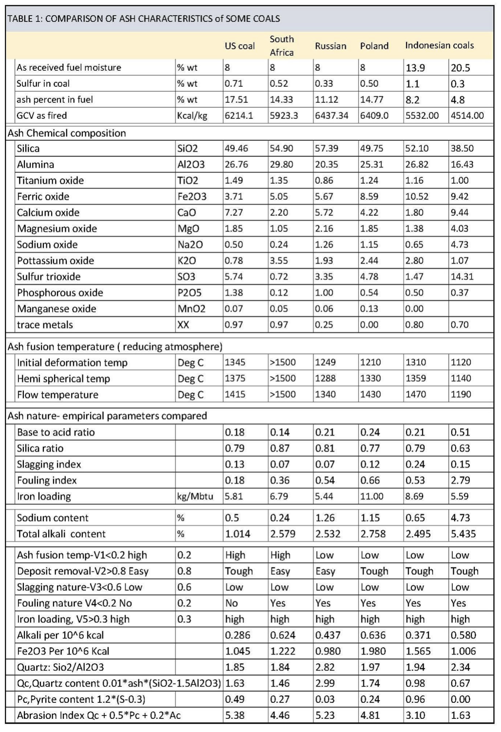
Coal is excavated along with various non-coal materials, termed mineral matter. The mineral matter gets oxidized during combustion. It is customary to analyse the chemical constituents of the ash as listed in table 1.
The fusion temperature of the ash should be above 1200°C. There are coals with low ash fusion temperatures of around 1000°C. Such coals require attention to combustion temperature in the furnace. There are standard procedures to test the ash fusion temperature of coal ash. One such procedure is outlined in ASTM D 1857 / ISO 540. However, for practical purposes, the coal ash can be tested in a lab furnace to know its suitability to fire in the boiler and to understand the limiting combustion temperature. The Ash content of coal is mostly tested at the plant lab. This ash can be placed at 1200°C to know if it is agglomerating or not. In case the ash melts at a lower temperature, the ash would become a hard particle and would affect the erosion of the furnace wall panel. Such erosion will be a gross erosion of the wall tubes.
Operating temperature of the CFBC furnace
The operating temperature of the CFBC furnace is dependent on how much evaporating and superheating surfaces are placed in the furnace. In addition, the furnace heat absorption is a function of the fines content in the circulating bed ash/material. Heat transfer in the upper furnace is dependent on the number of fines in the upper furnace. The fines content is influenced by many factors. They are:
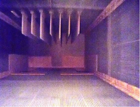
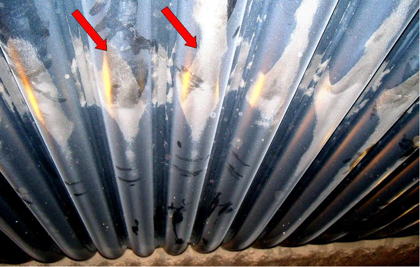
- Ash content in coal: When the ash content is less than 8%, there can be less fine particle addition from ash. This may not match the depletion from the furnace. This would result in less upper furnace inventory and thus leads to higher combustion temperature. Upper furnace inventory is known by the difference in furnace pressures between the kick-off zone and cyclone inlet. This is usually in the range of 80 -125 mm WC. Photo 1 shows the case with sufficient solids in the upper furnace.
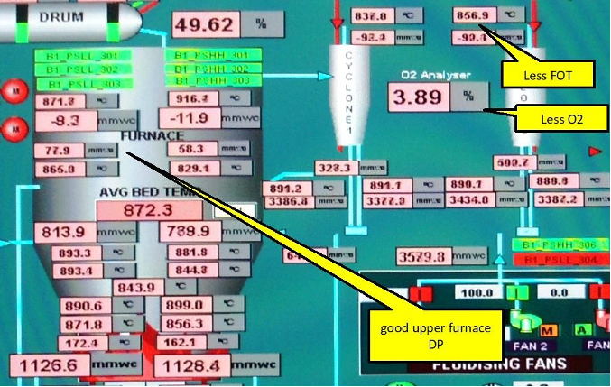
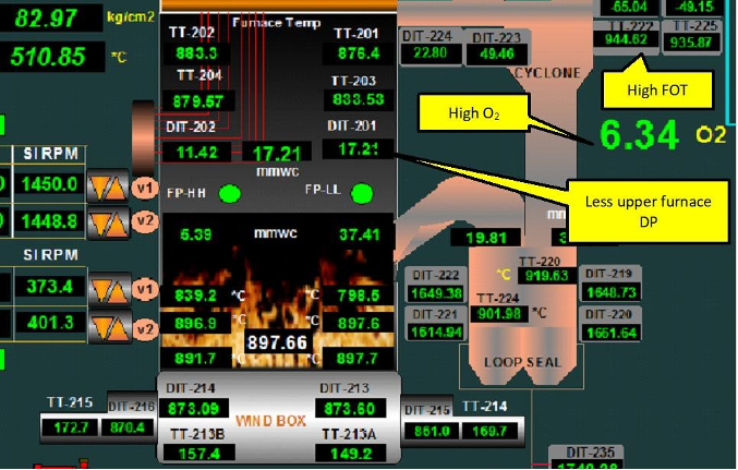
Photo 2 shows the case where the upper furnace DP is 17 mm WC. Less upper furnace DP leads to high FOT and demands high oxygen % to keep the temperature under control. Operation with high EA increases the erosion rate.
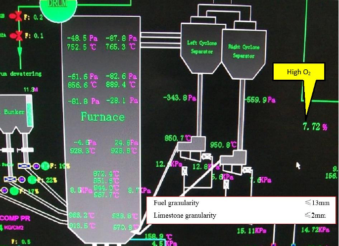
- Feed coal particle size distribution: Depending on the top size of coal particles from the coal handling plant, fines percentage will be present in the feed coal. High ash coals would have hard ash particles which do not break down in the furnace. Fewer fines in the input coal would lead to high combustion temperatures. Loop seal temperature & furnace exit gas temperatures run high. See photo 3 showing the wide temperature profile & high oxygen % due to the use of high-size particles as specified by the boiler maker.
- Percentage sorbent (limestone) addition: For sulphur-containing fuels, limestone is used for SOx capture. The fineness and composition and the percentage addition would decide the combustion temperature.
- Cyclone collection efficiency/cut-off particle size- the design of the cyclone is critical for low ash coals. When the fines leave the furnace, the combustion temperature would raise. Fly ash particle sieve analysis proves the efficiency of cyclones. Radial and volute entry configurations have been used by the boiler makers. Volute entry with proper velocity would have the best collection efficiency. Boilers with less ash input need an efficient cyclone. In one case, the cyclone profile changed by us to improve the collection efficiency. Figures 1 & 2 show two cases with poor cyclone design.
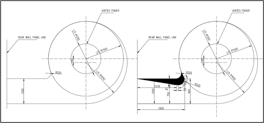
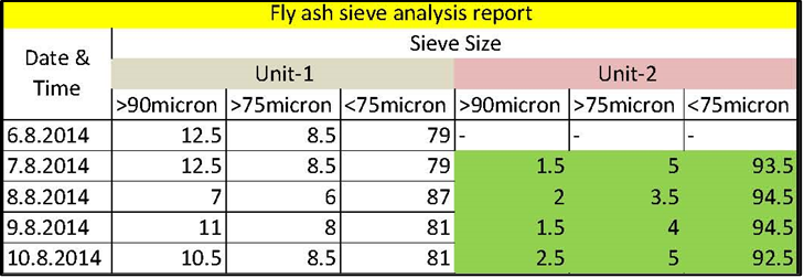
We recommend the fly ash is regularly monitored by sieve analysis. See a sample report.
- Ash removal rate from furnace/loop seal – inadvertent excess draining of bed material leads to high combustion temperature. A brief period with high furnace temperature can turn the ash to fuse and become harder.
Make-up bed material
The make-up of bed material will be required for low ash coals and in cases, where the cyclone collection efficiency is not designed as per low ash input from coal. In case the bed material contains minerals that fuse at low temperatures, then the bed ash becomes harder. The hardness of the bed ash will increase the rate of erosion.
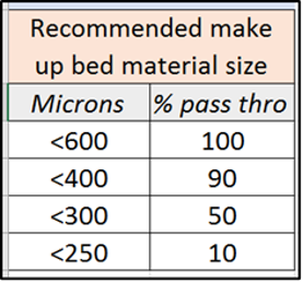
Make-up bed material should have a fusion temperature above 1200°C. The particle size range for a start-up can be 0.5 to 2.35 mm. However, for make-up purposes, the bed material should be < 600 microns. See the recommendation in the table here.
Bed ash reclamation and external recycling system
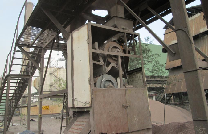
CFBC boilers fired with low ash coals are sometimes equipped with a bed ash reclamation system. Such a system should have a magnet system to separate iron from the ash. This depends on the coal. If the coal contains pyrite, such a system is required. There have been cases where the 3mm sq. screen size had been selected. The screen opening size can be 1.5mm sq. only. Photo 4 shows a bed material ash reclamation system with a magnetic separator.
Bed ash parameters to check
Whatever the coal-fired or bed material used or sorbent used, ultimately there are some bed ash parameters to be monitored to prevent erosion damage to the furnace wall tubes/wingwall evaporator/wingwall SH panels. They are:
- Bed ash bulk density: Bed ash bulk density is usually in the range of 1400-1450 kg/m3 due to high fines being retained in the furnace. Yet when the ash contains high iron (usually comes into the boiler as pyrite), the bulk density can reach 1650 kg/m3. The erosion rate of the furnace wall tubes will be higher due to iron accumulation.
- Bed ash iron content: As explained above the iron that comes as pyrite tends to accumulate in the furnace. This increases the erosion rate of the furnace tubes. This will be a gross erosion. It is a must that iron particles are restricted to 10%. The iron particles are to be separated by a magnet
- Bed ash sieve analysis: There had been a mistake in particle specification by some boiler makers. The coal handling plant should be selected without a pre-screen system in the case of low HGI coals. Different coals produce different fines percentage on crushing, for CFBC, fines are preferred. In case of a higher percentage of coarser particles, say +3 mm, the bed expansion is limited. This leads to high bed temperature. In addition, coarser particles cause a high erosion rate. It is a general requirement that all particles are less than 6 mm with minus 1 mm in between 30% & 40%. By draining in a controlled manner, the coarser particles can be taken out of the furnace inventory. Large-size drain pipes tend to remove fines also from the bed. Gates should be throttled so that only coarser particles are taken out.
Loop seal malfunctioning
- Higher capacity boilers are fitted with two cyclones. In case a loop seal is plugged, the bed temperature would rise. This causes the bed material to become harder. The boiler may continue to generate rated steam with the rise in furnace temperature. There are cases of fallen vortex finder and the boiler continuing to operate.
- In the case of a single cyclone, the transfer rate could be disturbed due to partial plugging. On full plugging of the loop seal, there will be an uncontrollable bed temperature rise. This can be known only by proper and adequate instrumentation at the loop seal. Due to partial plugging, the bed temperature can rise. Plugging can occur due to any of the following reasons:
- Nature of sorbent
- Inadequate airflow at the loop seal
- Plugging of the air nozzle
- Failure of air nozzle and filling of loop seal windbox
- Refractory spalled from above or at the loop seal itself and affecting material transfer
Inlet configuration to cyclone preferential erosion of side walls
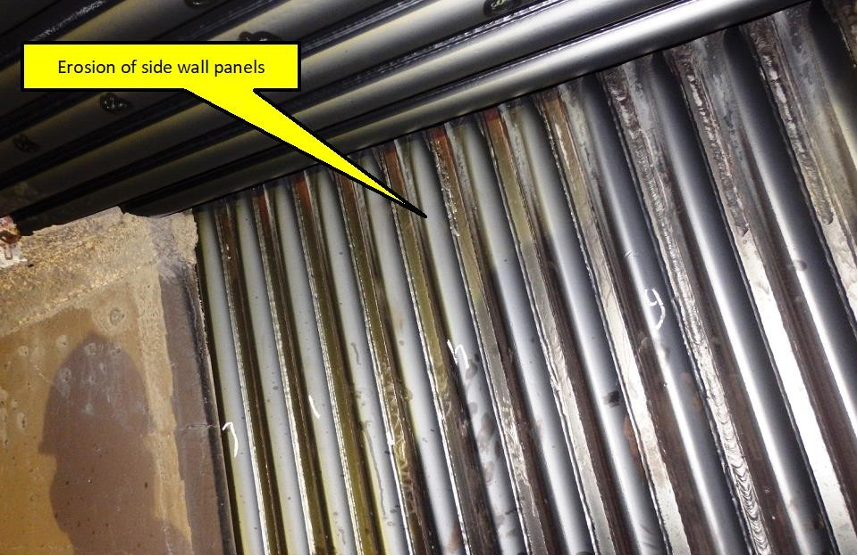
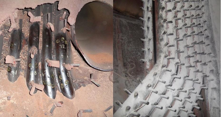
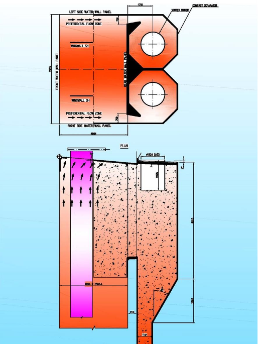
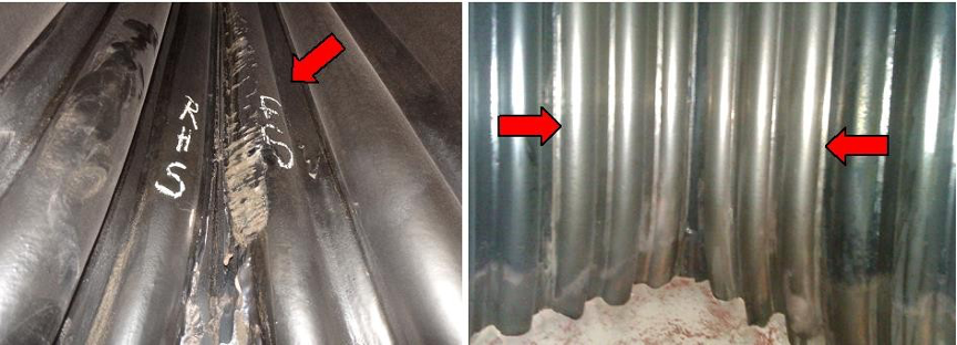
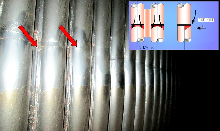
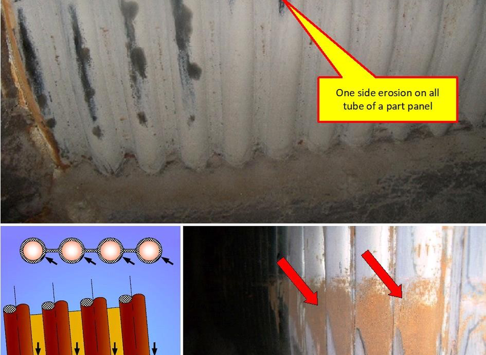
- The gas inlet configuration to cyclones can cause erosion of the side walls. See figure 3. The gas flows along the side walls before entering into the cyclones. The side wall panel gets eroded due to this effect. See photo 6 showing the side wall erosion.
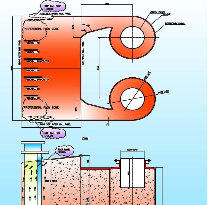
- The cyclone inlet wall angle can be altered as in figure 4. Some manufacturers are yet to adopt this feature.
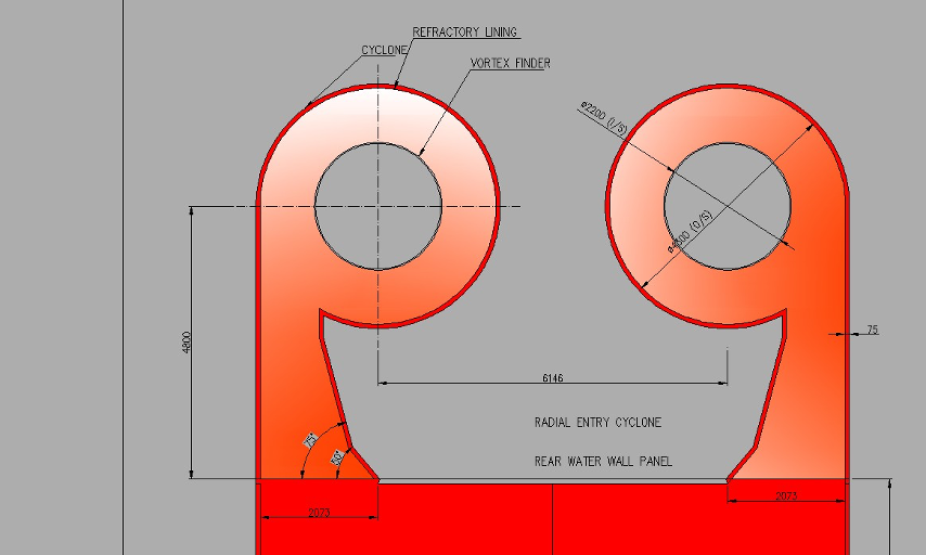
- In figure 5, the cyclone entry is at the centre. This may cause the material to drop out along the side walls, depending on the % width open at the rear wall. Not all the bed inventory enters cyclones. Some fall out of the stream. This causes internal recirculation of solids. This is why some parts of the side walls and rear wall panels are refractory-lined.
Arrangement of wingwall panels
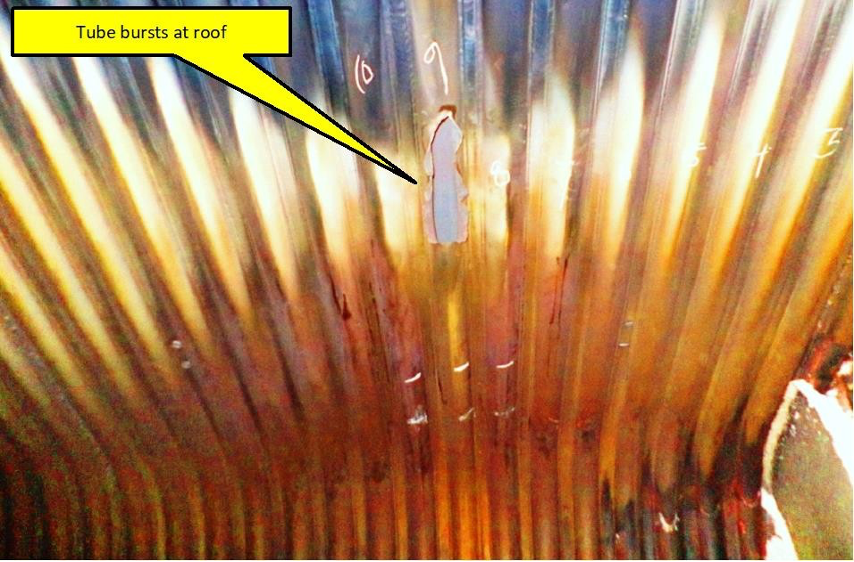
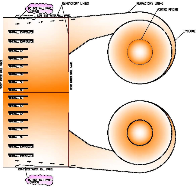
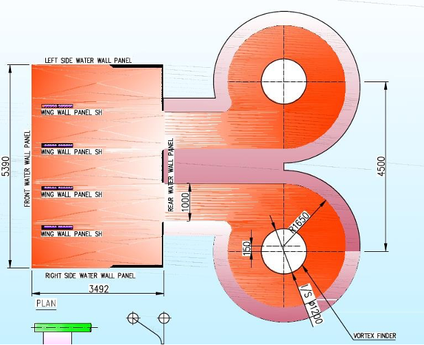
The arrangement of the wingwall panels should be equally spaced. Too close spacing can cause preferential internal recirculation of solids. Figure 3 shows the boiler, wherein the uneven arrangement of wingwall panels has resulted in preferential gas flow and resulted in thinning down of the roof tubes. Photo 8 shows the roof tube failure in the above case.
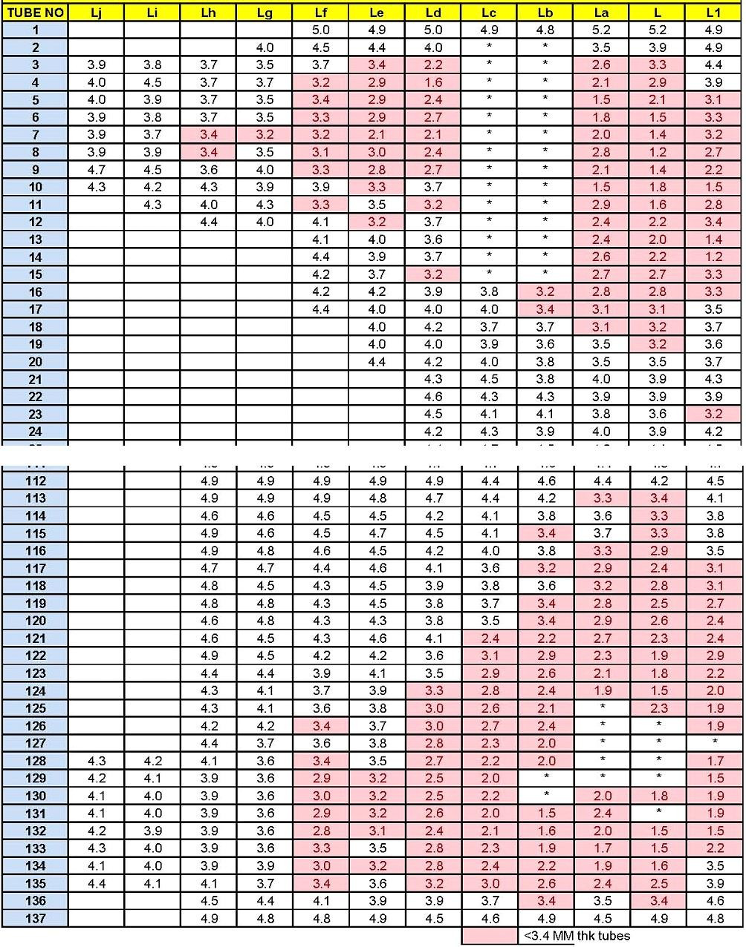
Figure 6 shows the thickness mapping when the erosion failure occurred at this boiler. Around 20 tubes from each side wall only show up erosion. The thinning has taken place within 2 years of boiler operation.
Narrow inlet configuration to cyclone-preferential erosion of side walls.
The gas inlet configuration shown in figure 7 is a bit odd. There will be a fallout of material between the two gas flow paths at cyclone entry. This is because the gas flow opening width is much less compared to the width of the rear wall. The rear wall is subject to high recirculation of solids. The heat pick-up pattern also can be different due to this. As the gas flow is along the side wall panel, the entire side panels would need protective refractory lining.
Improper refractory lining
Refractory lining defects fall into the following subcategories.
- Refractory design at the lower furnace
- The anchor design adopted with thick refractory lining had been subject to thermal spalling due to heating and cooling cycles. A tube leak is sufficient to create damage to the refractory. See photo 9.
Photos 9 & 10: The left side photo shows the V-type anchor welded to panel tubes. The refractory spalls off easily since the refractory thickness should be at least 75 mm from the tube crown. The right-side photo shows the stud’s design. This design is superior. Refractory repair is simpler. A thin layer of plastic refractory is found to be adequate during maintenance.
- There are cases of improper refractory design at the lower part of the furnace. Of all the designs adopted the use of LC castable with studs welded to tubes proved to be the best. See photo 10. However, high alumina plastic refractory is desirable around the fuel feed opening and other openings.
- One manufacturer provides a multilayer design, which is the worst design of all from the maintenance point of view. See figure 8 & photo 11.
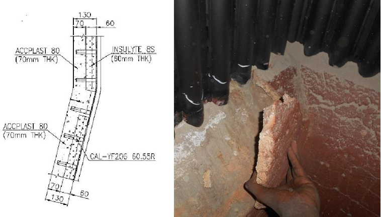
Figure 8 & Photo11: The above refractory detail adopted by one manufacturer is the most complex refractory we have seen. The entire refractory had to be done all over again due to this poor design. The design is not suited for quick thermal cycling/occasional high-temperature excursions and large temperature swings during a tube leak. A tube leak is unavoidable. If it happens, the design should not demand total refractory rework. We find the stud design with 50 mm thick LC castable is found to be good. 10 mm thick plastic-refractory overcoat is seen to be good enough during maintenance.
- Refractory spalling due to thick sections
- Thick refractory sections in excess of 50 mm may be used for the various openings such as fuel feed points, SA ports, ash recycle openings and start-up burners would spall and create havoc. The tubes get exposed locally and are subject to localized erosion. This is frequently seen during shutdown inspections. See photo 12.
- The spalled refractory blocks lead to erosion failure of air nozzles. This is quite a dangerous situation leading to hotbed material pouring into the windbox. See photos 13 & 14.
- Improper refractory geometry at corners
- CFBC combustors are invariable of the rectangular cross-section. The upward gas flow is at the centre and the particle downflow is high along the wall. The erosion rate has to be monitored in CFBC boilers on every annual shutdown. This is not the case with other combustion technologies. Generally, fins cannot be closed accurately at the corners. This also adds to local fin-tube profile defects. See photos 15 & 16 showing corner tube erosion. Some manufacturers provide corner refractory. Some boiler makers do not provide this.
- The cyclone entry geometry causes preferential erosion along the front wall corners. Low load operation enhances this effect. This also demands furnace corner refractory.
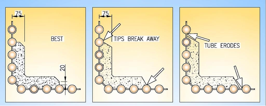
- Where the furnace corner refractory is provided, improper geometry is adopted by some boiler makers. The good and bad corner refractory details are illustrated in figure 9.
- Refractory ends cannot be finished with thin edges. Thin edges simply break away and create zig-zag paths for material flow. Localized craters are created on the tubes in this area. See photos 17 & 18.
- Improper refractory geometry at kick-off bend zone
- The Kick-off zone is a design detail added to CFBC combustor during the development & scale-up process. Some designs do not have this, instead, alternate arrangements are provided. As the particles travel down at good speed, the refractory applies a brake. The dissipation of kinetic energy causes the erosion of both refractory & tubes nearby. When the refractory is in excess, the refractory erodes. Due to installation mistakes in refractory contour, the tubes can erode. See photos 19 & 20 showing the erosion of the refractory and tube. Figures 10 -12 show the refractory profile requirement at the kick-off zone. It is recommended to have 90% alumina plastic refractory at the kick-off zone (around 500 mm height) to slow down the erosion rate of refractory.
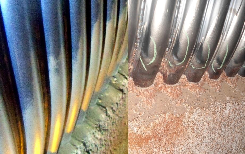
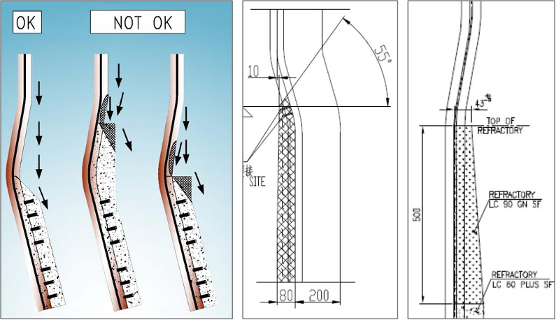
Figure 10-12: The above are the details of other boiler makers. If there is excess refractory, the waterfall at the kickoff zone erodes faster. The accuracy of construction is very important. The flow of solids should be free & unobstructed.
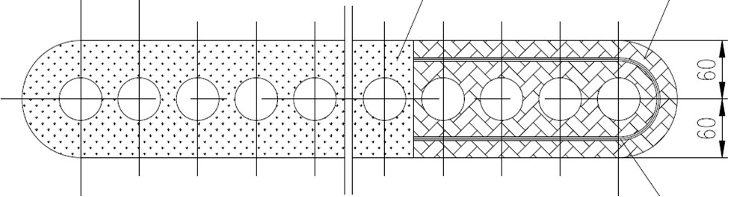
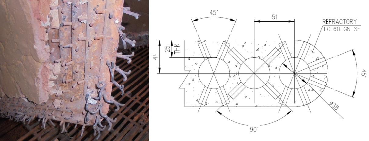
- Improper anchor design/excess refractory at wingwall evaporator/superheater at bottom
- Except for the vertical part of the wingwall panels, the rest of the panel is covered with LC refractory or plastic refractory. This should be a thin refractory with adequate studs, any other details would fail. See photos 21 & 22 showing improper protection. Figure 13 shows the improper engineering of the wingwall SH / Evaporator bottom tube protection system. When the studs are inadequate or when the refractory thickness is excess, spalling is encountered. Then the bottommost tube of the wingwall evaporator / SH fails by erosion. If the refractory thickness is more than 40 mm there is a vulnerability to spalling. See photo 23 showing the spalling of refractory due to excess refractory. Figure 14 shows the correct refractory detail to be followed.
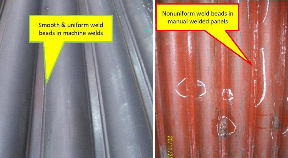
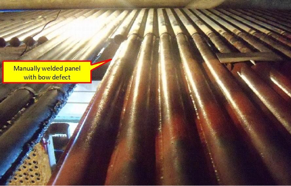
Improper panel manufacture – erosion due to manufacturing defects
- Not every manufacturer is clear on this. Unlike the PF boiler / AFBC boiler / stoker-fired boilers/gas or oil-fired boilers, CFBC furnace panels demand stringent quality levels during manufacture & during fieldwork. Manually welded panels are not acceptable. Only panels made by automatic welding machines are to be used. Panels coming under refractory lining can be made by the manual welding process. Figure 15 states the important quality requirements during the production & construction stage.
Manufacturing and erection notes for CFBC furnace panels:
- The panel should be manufactured using an automatic SAW machine or an Automatic MIG welding machine.
- All tube and fin butt welds are to be flush ground smooth only on the fireside.
- After completing the fin-to-fin butt weld from the outside, the inside seal run is to be done before grinding smoothly.
- No knots are permitted in tube–fin welding. Weld should be uniform.
- Tubes should be parallel and well-aligned.
- The panel shall be free of bow and twist.
- Panels should be erected to plumb.
- The diagonal distance of panels shall not deviate by more than 5 mm.
Figure 15: The above notes are important ones for the CFBC panel manufacture and erection at the field. Note no. 3 and 7 are specific to fieldwork.
- Several defects such as out-of-alignment tubes & fins, excess welding at fins, non-removal of tube & fin butt weld beads, and bowing of panels cause preferential erosion. These are explained in this article.
Improper erection of furnace wall panels
Not all erection engineers or erection contractors are clear on the quality requirements of the furnace panel assembly. Furnace wall panels are sent in parts due to transport and erection constraints. Fieldwork demands stringent quality levels. Some of the serious defects and their effects are listed here.
- Failure to remove the tube & fin buttweld beads leads to localized erosion patterns that ultimately lead to tube failure at the fin-tube weldments. This is illustrated in Figures 16-18. Photos 24-27 show real-life examples.
- Fin filler plates are to be properly placed in the plane. The welds should be of full penetration welds and the excess beads are to be ground off. Portable pencil grinders/carbide cutting tools are to be used to remove the weld beads on the fireside. Photos 24 & 27 show the detrimental effect of the defects
- Panel fins which are slit for alignment purposes are to be sealed with full penetration welds. The beads are to be ground flush afterwards. Generally during construction, the panel-to-panel weldments are carried out from outside the furnace. CFBC boiler demands scaffolding inside in order to carry out full penetration welds and to flush grind all the tube-to-tube butt weldments, fin-to-fin butt weldments, and fin closures at field joints.
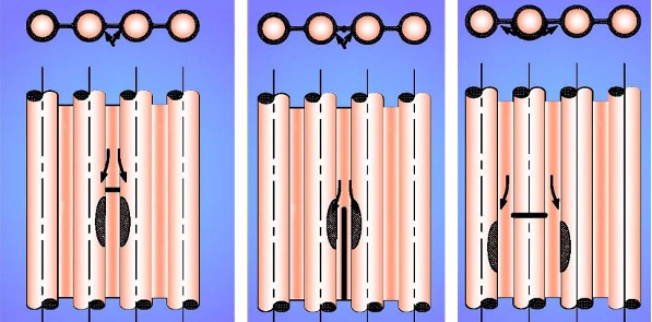
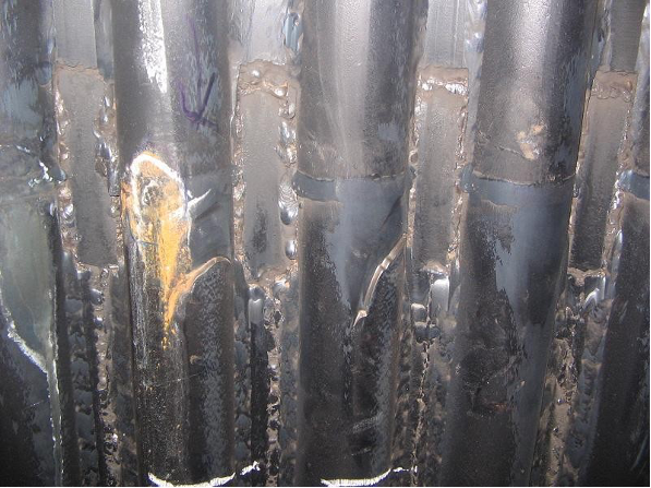
- The furnace wall panels have to be absolutely vertical in both Y-Z planes. Failure to maintain verticality leads to gross erosion of panels. Photo 28 shows the erosion of tubes near the field weld, where vertical alignment is compromised. Figure 19 shows the mechanism. See photo 29 showing the localized panel erosion due to the presence of a bow in the panel. On one wall, just one panel may alone get eroded in a peculiar manner when verticality is compromised. See photos 30 & 31 showing the patch erosion due to the out-of-verticality defect. Figure 20 illustrates the mechanism.
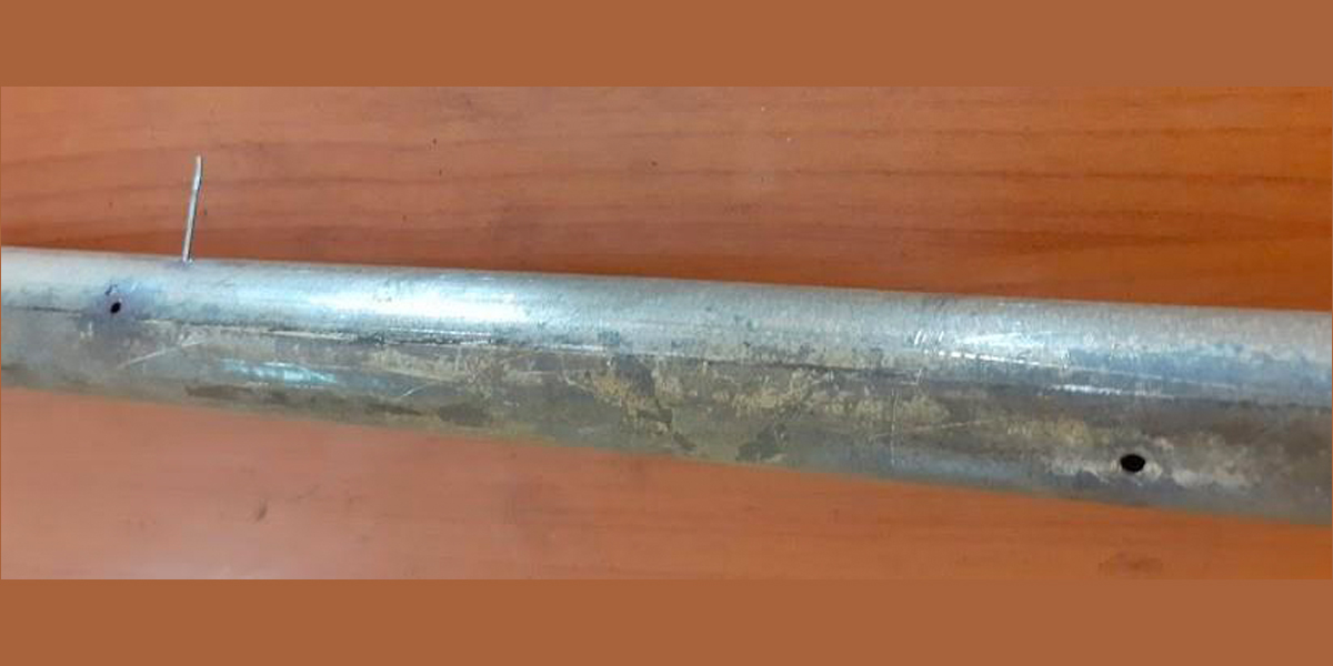
- No scrap can be left on the fire side anywhere. Or else local failure will be encountered. Even a thermocouple inserted in the furnace will be subject to erosion. Not only the thermocouple would be cut, but also the panel tubes nearby will be eroded off. Photo 32 shows the panel tube erosion near the thermocouple insertion point. Figure 21 illustrates the mechanism. Retractable thermocouples are recommended below the wingwall SH for start-up flue gas temperature control purposes.
- Pressure tapping is permitted in the CFBC combustor. Again, the tapping should be flush with the fin.
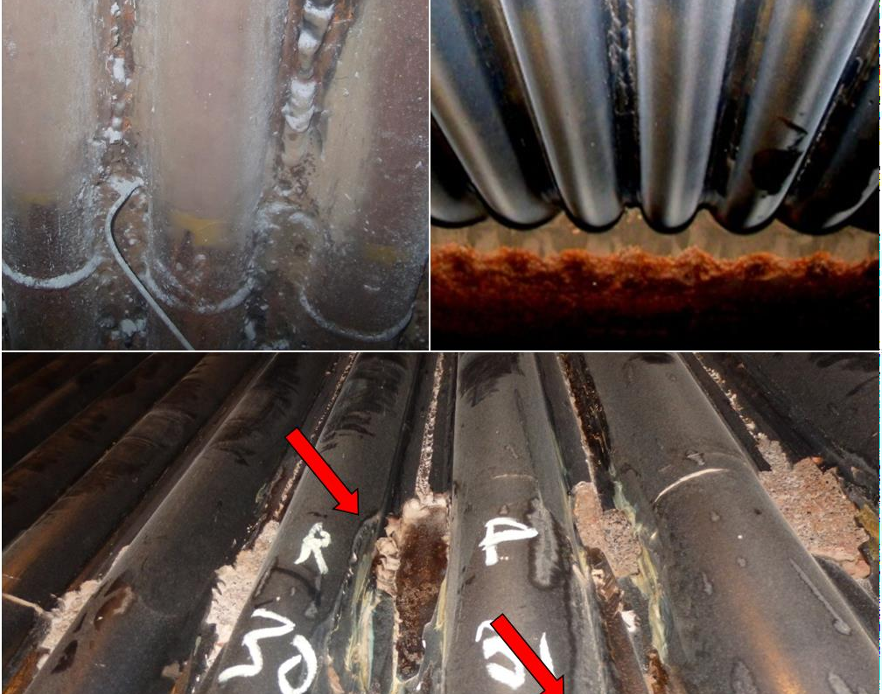
- Periodical replacement of panels may be required in CFBC boilers. The replacements may be warranted within a period of 5 years depending on the coal ash particle abrasiveness and other construction defects. Usually, the replacement will be a length of 5 m from the bottom tapered panels. Such replacement panels are also to be fabricated using a mechanized panel manufacturing machine with auto SAW or auto MIG technology. A compromise results in frequent outages. See photos 33-35 driving the point.
Improper metal spray
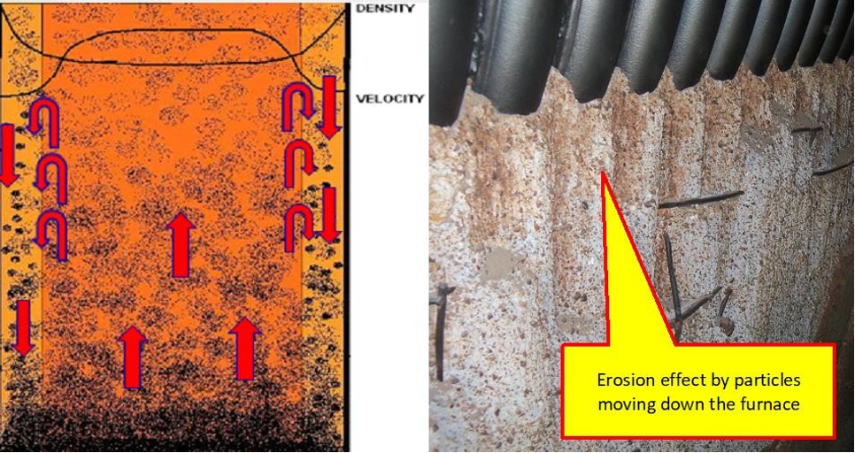
- Metal spray technology had been developed for reconditioning worn-out components in several industries. This has been extended to CFBC boilers. Some boiler makers apply this technology to furnace wall panels that come above the kick-off zone. This is the place where the panels have a shorter life. This is because the velocity & particle density is maximum here. See figure 22, showing the flow of solids in the CFBC furnace. Photo 36 shows the erosion effect on the kick-off zone refractory.
- HVOF spray with wear-resistant materials to a thickness of 100-150 microns has been tried by many. Field application had been a disaster. This is because HVOF spray cannot be applied properly by the manual process in field conditions. Improper angle & distance and non-uniform layer thickness have led to miserable failure. Even panels with the first supply of HVOF spray had failed in 3 years’ time. See photos 37-39 showing actual experience from two different plants.
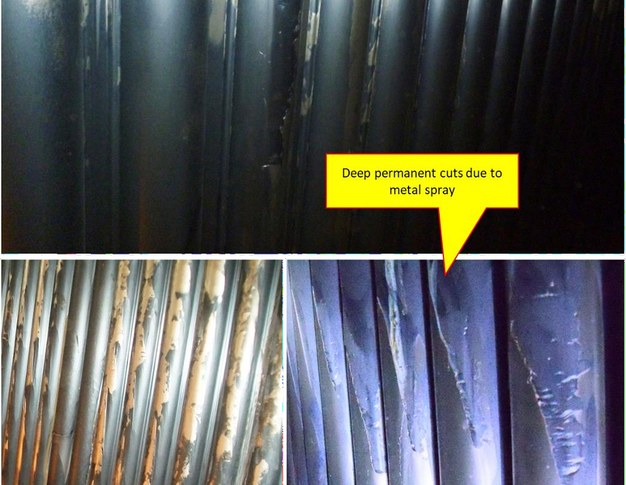
- Users who have tried under field conditions revert back to regular furnace panels. This gives longer life as compared to the metal sprayed panels.
Part load operation
Part load operation results in the internal recirculation of solids within the furnace. The flow through the cyclone & loop seal would reduce. In the case of two cyclone systems, there can be high temperatures at one loop seal due to short-circuiting of gas from the furnace to the loop seal. This is noted by the difference in loop seal temperature. The material flow pattern is not predictable. The prolonged operations can cause issues. There are cases that one or two walls appear to be polished.
Deviation from design fuels
The design of furnace, cyclone & loop seal etc. are designed for a specified fuel. The gas quantity can largely differ when high moisture / low GCV fuels are fired. There are cases where the design moisture is 10% and as-fired moisture is 30% – 38%. The flue gas velocity could be higher causing a high erosion rate at the target zone of the cyclone. Design fuels should be specified on air dried basis instead of a received basis. This is particularly applicable to Indonesian coals.
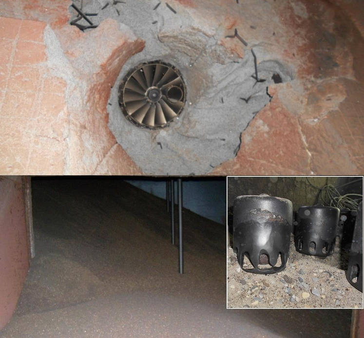
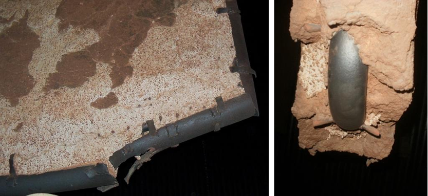
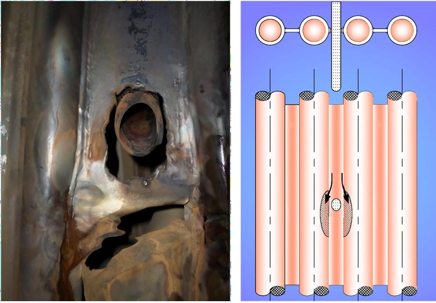
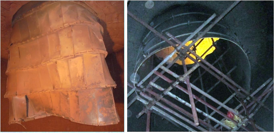
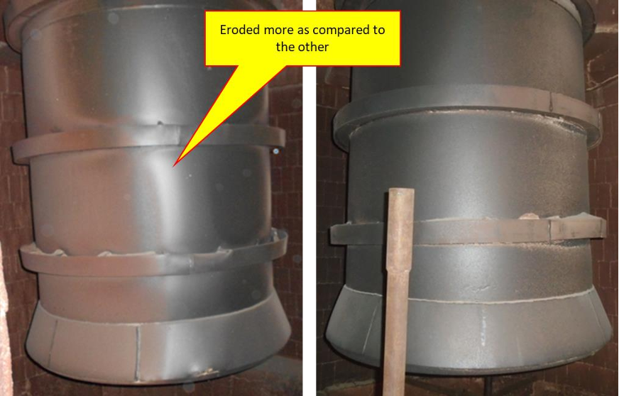
Malfunctioning of the vortex finder
The vortex finder can be subject to distortion due to tube leaks. See photos 40 & 41. The vortex finder may be subject to distortion due to constraints in thermal expansion. This leads to differential gas flow between the cyclones. This leads to unbalanced gas flow within the furnace. It can result in short-circuiting of flue gas through the loop seal. This can also show up the difference in the erosion pattern of the furnace wall panels. It is seen that the cyclones show up differences in erosion patterns.
Variation in gas flow between cyclone-cyclone construction
The cyclone can be made from steam-cooled tubes or water-cooled tubes or it can be of refractory construction. The most important part of the cyclone is the bull nose in the cyclones, in the case of refractory construction. Differences in opening dimensions/shape can cause differential gas flow. There will be differences in collection rates of ash between cyclones. This will cause internal recirculation of solids within the furnace. There will be uneven erosion of the refractory. Photo 42 & 43 shows the erosion of the vortex finder. The refractory erosion showed a large difference between the two cyclones.
Variation in gas flow between cyclones- inadequate upper furnace density / DP
When the upper furnace inventory is less the loop seals show the difference in temperature. The collection rate would be different, this is due to inadequate resistance for the gas flow. Short-circuiting of flue gas takes place as the flow of solids in the down leg will be less.
Imbalance in fuel feeding
A number of fuel feed points are provided in the design to distribute the fuel equally, in this way, the air is well distributed by grid nozzles and SA ports. Some boiler engineers ignore this and choose to feed coal with large unbalance. This can cause preferential internal circulation of the solids.
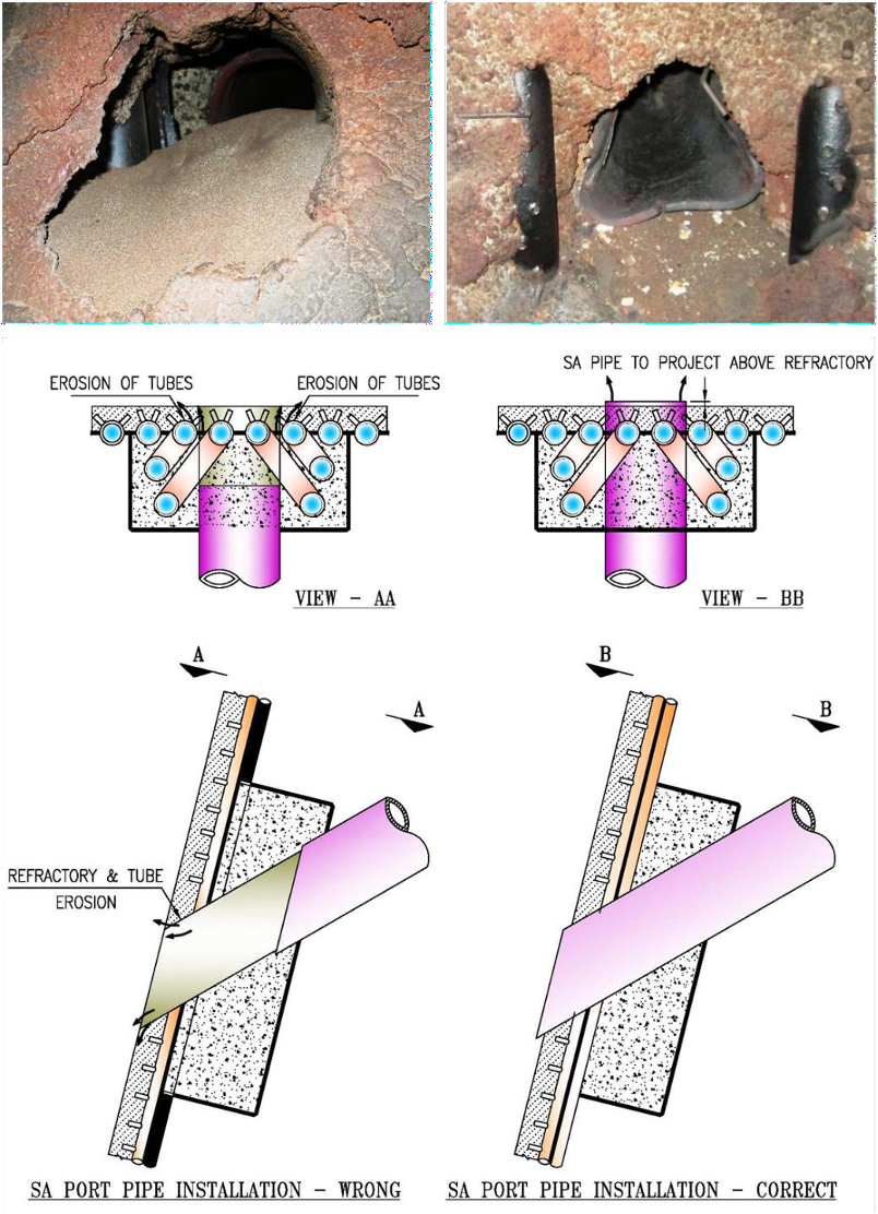
Erosion of furnace tubes around SA ports
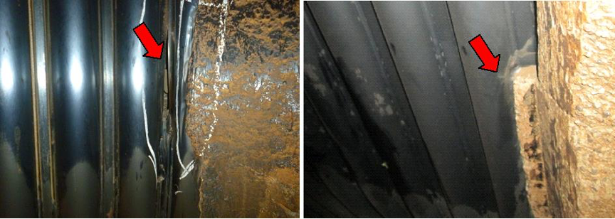
SA nozzles setting should be projected inside the furnace to a minimum length. In cases where the nozzles are left inside the refractory seal box, the refractory erodes / spalls over a period. Subsequently, the tubes around the SA port opening begin to erode. See photos 44 & 45 and figure 23.
Erosion protection for furnace wall panel above Wingwall SH / Evaporator openings
As discussed earlier, any protrusion in the furnace walls would be subject to erosion. For this reason, the wingwall SH and wingwall evaporator are covered with high alumina refractory at the penetrations. Now the refractory itself becomes a disturbing element causing the panel tube erosion. See figure 24 and Photos 46 & 47 emphasizing the point. The erosion protection is chosen between weld overlay and HVOF spray.
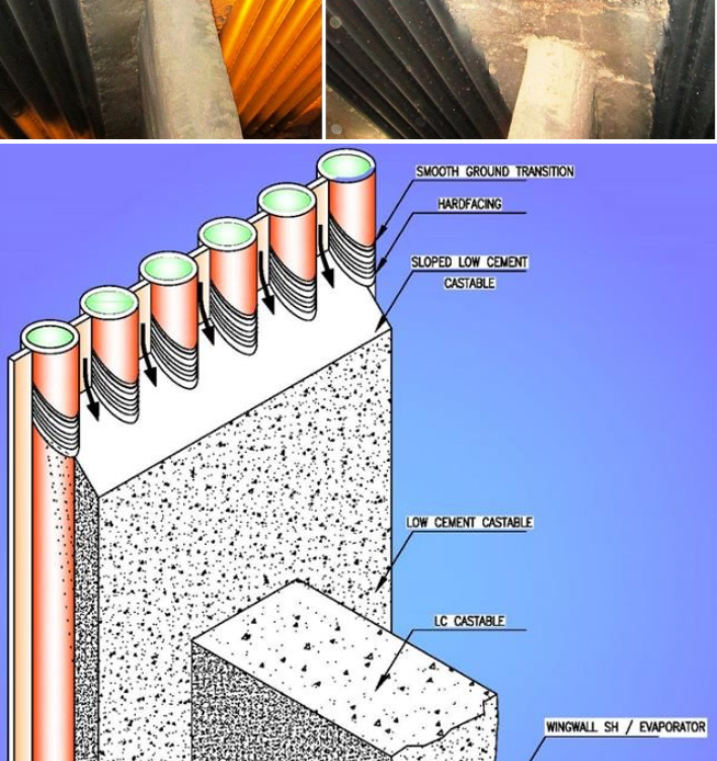
Photo 46 & 47; Figure 24:
- Photos above show the possibility of moustache erosion along the refractory to tube interface. The figure illustrates the solid flow which causes localized erosion of tubes.
- Weld overlaying is adopted here. HVOF metal spray can be adopted only if proper working conditions are made available.
- Metal spray or weld overlay is required for 200 mm length. The overlay should be completed before applying the refractory since a 50-mm overlap is a must between the refractory and the overlay.
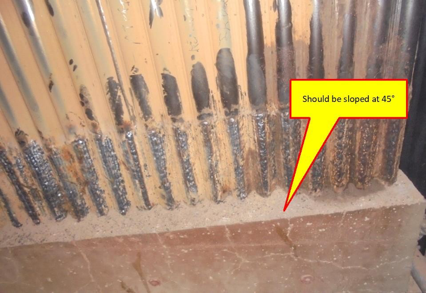
- Theslopedrefractoryfaceisimportant to reduce the erosion rate. The contouring of refractory along the tube is important as required for furnace corner refractory.
- Weld overlay is seen to last longer. The only care is to be taken to have a smooth transition between the bare tube and the overlaid portion.
- Metal spray or weld overlay is found required for 200 mm length. The overlay has to be completed before applying the refractory since a 50-mm overlapping is a must between the refractory and the overlay.
- HVOF metal spray can be adopted only if proper working conditions are made available.
- The sloped refractory face is important to reduce the erosion rate.
- The contouring of refractory along the tube is important as required for furnace corner refractory.
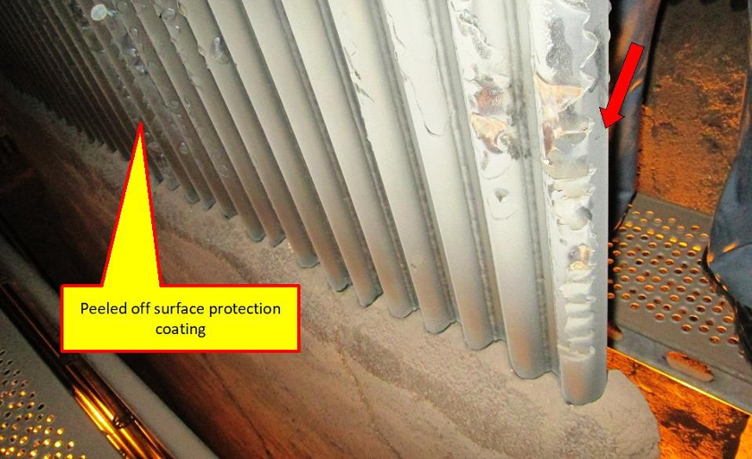
Erosion protection of Wingwall SH / Evaporator above the refractory
The wingwall SH or evaporators are protected from erosion at the bottom zone. This is specifically required as the wingwall SH / Evaporator tubes are oriented horizontally to the solids flow direction. Once the tubes are oriented vertically the erosion rate is greatly reduced. However, the transition zone between the refractory and the vertical tubes is susceptible to erosion. In this zone, metal spray or HVOF spray is applied. See photos 48 & 49. HVOF metal spray has its limitation with respect to dry heating during start-up. Field repair is not successful unless it is executed with the complete removal of the previous coating. Weld overlay is found to be simpler. The transition zone between the weld overlay and the bare tube should be ground smooth. The refractory should be sloped at 45° to allow the free flow of solids.
Limestone chemistry
There are boilers which use petcoke. Petcoke contains high sulphur. In order to limit SOx emission, limestone is fed along with petcoke. The quality of the limestone could vary from location to location to large extent. Petcoke does not contain ash. Hence the bed inventory is made of limestone in this case. The silica and alumina content decide the baking effect at the loop seal down-leg and the flowability in the loop seal outlet duct. The inserts available in limestone improve the flowability of solids. There are cases where the flowability of ash had been poor. This results in partial plugging / full plugging of the loop seal. If this is not noticed, there can be high internal solids circulation within the furnace. This can increase the erosion rate depending on the inert content of limestone.
Conclusion
The CFBC technology is opted to reduce the unburnt carbon levels in fly ash so that the ash becomes usable in the cement industry. The gain in efficiency is a matter of how much is the ash content and what is the GCV of fuel. CFBC boiler needs high-head PA, SA and ID fans and hence the auxiliary power consumption is high. Yet a user knowingly opts for CFBC for the benefit of carbon loss. We have compiled our observations from the design / operational / shutdown auditing of several CFBC installations and presented them here. Boiler manufacturers are required to give a good installation without the defects highlighted in this article.

Anil Vyas
October 26, 2023 at 6:45 amVery interesting article sir.