While using reciprocating pumps for handling high-temperature fluids, it is imperative to consider three major aspects: Cavitation, Liquid Separation, and Flashing. It is also extremely important to create appropriate site conditions which will support the pump performance.
1. Cavitation:
Cavitation occurs when Net Positive Suction Head Available, NPSHA becomes lesser than the Net Positive Suction Head Required, NPSHR of the pump. This means that the fluid pressure drops below its vapor pressure. This results in undue noise/vibration and pulsations in the pump which is evident from the fluctuation/flickering of the pressure gauge needle (if fitted on the pump). Globally, the pumping consultants recommend a minimum gap of 0.5m between NPSHA and NPSHR for the satisfactory performance of the pumps. (This is also called ‘Field Correction’). Cavitation can create pinholes and can damage the suction side piping as well as accessories along with the pump itself.
It is extremely difficult to calculate the exact NPSHA at each site as the infrastructural conditions are not identical.
The NPSHA figure depends on the following major elements:
- Geographical location; the height of the installation from the mean sea level
- Temperature of the fluid being handled and its vapor pressure
- Height of the suction tank
- Minimum height of fluid above the suction pipe intersection of the suction tank
- Total length of suction piping
- Inner diameter of the suction pipe
- Total number and types of bends (long/short)
- Pressure drops across all other accessories between the suction tank and the pump like economizer, optimizer, inline filter, etc.
The NPSHR figure depends on the following major elements:
- Piston/plunger diameter
- Net operating pump speed
It is also influenced by the pressure drop across the suction passages and inlet valve assemblies.
2. Liquid separation and flashing:
The higher pump speed makes the plungers move backward quickly when the fluid from the suction line is not able to closely follow the plungers. This creates a gap between the liquid and the plunger which gets filled by the liquid-vapor. These vapor bubbles collapse during the pressure stroke causing undue noise/vibrations along with the drop in the pump output/flow. This is termed Flashing. A higher piston/plunger diameter sucks a higher amount of fluid during each stroke. Pump design must take into consideration the optimization of piston/plunger diameter and suction valve size. Thus, it is important to look at the total resistance offered by the pump itself before the fluid can touch the plungers.
Kindly note that 1 and 2 above are very closely connected. The main difference is that cavitation can initiate and hence can damage parts/accessories/piping on the suction side of the pump whereas liquid separation is something that essentially happens ‘inside’ the pump.
3. Present conditions/challenges:
It is said that ‘boiler is the heart of process plant’ and ‘feed pump is the heart of boiler’. Unfortunately, Reciprocating Boiler Feed Pump does not receive the kind of attention it deserves. Boiler manufacturers should prefer industrial pumps and should not focus on the small/negligible price difference as ultimately it is a cost for quality. The pumps designed and manufactured for spraying/cleaning applications must be properly scrutinized.
A. Selection of make and model:
It is extremely important to select the right make and model. We must ensure that the manufacturer has the following minimum capabilities:
a. Data Backup:
- G.A. and C.S. drawings (or exploded view)
- Part-list
- Component drawings with a clear indication of material of construction, machining tolerance and sequence, surface treatment, etc.
- Raw material test reports and co-relation
- Head-capacity (H-Q) curves and NPSHR curves
- Pump test reports (at least 5-year-old records)
- Corrective and preventive action charts
- Installation, commissioning, and maintenance manuals
- Qualified and experienced staff to support any type of non-standard requirements and technical queries
- Training for OEM/end-user staff
b. Manufacturing set-up:
- Fixtures for consistency of quality
- GO-NOGO gauges for checking all the important components
- Important machines like a hydraulic press for proper assembly work
- A calibrated close-loop testbed with calibrated instruments to measure speed, pressure, flow, current drawn, etc.
B. Site conditions/limitations:
- Lower suction tank height
- No clear understanding of ‘Total Pressure Drop’ between the suction tank and the pump. (Ref. 8 elements of NPSHA under 1)
- Lack of vital instrumentation (like a good pressure gauge)
- Most of the sites do not have good quality inline filters which offer higher filtration areas and can create clear signals for cleaning. The conventional Y-type strainers offer an exceptionally lower filtration cross-section area. This results in frequent clogging of the element resulting in all relevant and standard problems discussed above. Our site survey during the last 25 years has indicated that at many sites, the operators prefer to remove the filter element to avoid constant cleaning. The solid/opaque body of the Y-type strainer does not offer any indication of whether the filter element is fitted inside or is removed and kept aside. Most of our pumps are pushing rusty red water into the coils (transparent filters can show this.) From the cost perspective, the pump may have a little damage, but the boiler manufacturers must take a call as to what quality of water should enter the coil
- Trained manpower- as we understand, the non-IBR boiler operators do not need any ‘Specific National Level Certification’. There is a great amount of attrition in the skilled manpower segment. Many companies have reduced their focus on training. It is observed that often field representatives raise false alarms without referring to the important documents like parts catalog, O&M manual, troubleshooting charts, etc. The inability to troubleshoot can have serious long-term consequences.
- Availability of essential gadgets/instruments (with the service staff). The tachometer is an extremely important instrument as it indicates net pump speed. The pump flow is directly proportional to speed and hence even a small change in pump speed can affect the pump output. It is extremely important to understand that many pumping systems inputs like the voltage, frequency, motor full load speed, pulley quality, design, V-belt, etc. have a clear-cut effect on the net pump speed. In absence of the net pump speed figure, the pump most of the time is blamed for incorrect output (There is no point in blaming or troubleshooting the pump if the net pump speed varies from the standard recommended speed)
- A tachometer can easily help in identifying the actual problem area and helps in addressing the root cause. A compound gauge, tachometer/strobe, analog/digital thermometer, and a ‘close-loop flow test’ kit is allit takes. Put together this does not cost over INR 3000/- (This is a one-time investment, and each branch office/service franchisee can have this to be carried to the site by the service representative)
A gadget like a tachometer also comes in handy in the troubleshooting of electric motors, fans/blowers, agitators which are very common in use.
Effects of the above major considerations on the pump models:
A. Present standard models (85oC max) (Dampf Kolben make):
The design temperature (max) of all the present pump models is 85oC. This just means that all the components of the pumps can withstand this condition. Hence, the maximum operating inlet temperature is restricted to 80oC. As explained above, the NPSHA at any given point and at any site is difficult to calculate. This figure also can alter due to subsequent changes/modifications, carried out if any, between the suction tank and the pump. These parameters presently restrict the end-user to use the inlet water temperature above 60-70oC. In case the inlet water temperature is to be pushed ahead till 80oC, the best option is to use a glycerin-filled compound gauge (-1 to +1 bar) near the pump suction (approx. price of which is not more than INR 500). It would be mandatory to use a temperature sensor along with an analog/digital temperature indicator. It is also necessary to use a glycerin-filled pressure gauge on all the pumps (as a general practice, every process pump must a have calibrated pressure gauge fitted on it). The flickering/fluctuating needle of this gauge immediately indicates various root causes like inadequate suction pressure, clogged inlet filter, unduly higher suction water temperature, clogged valve assemblies, etc. For handling higher inlet water temperature above 70oC, it is highly recommended to shift to a ‘gadget/instrumentation’ based approach rather than a human one. Lastly, it is necessary to have the right quality and sizeof the inlet filter on the suction side of the pump.
1. Models BF-130 and BF-330:
These models use SS-304 Pistons (30mm diameter). These pistons because of their higher area of cross-section and metallic construction, conduct and carry the heat from the fluid to the oil inside the crankcase. The overheating can cause the oil to oxidize and cause a loss of lubricating properties. This can affect the life of crankshaft, connecting rods, and bearings.
Even a small degree of Cavitation/Flashing can expose the V-Packings (Gland Packings) to latent heat. This immediately damages the rubber and partial melting of the rubber surface creates a bond between individual V-Packings. When they melt and stick together, they fail to perform their duty and stuffing box leakage becomes imminent.
a. Cavitation: The piston diameter of the present Standard Triplex Pump (BF-330) is 30mm which pushes the NPSHR figure on the upside. This creates limitations for handling higher temperatures fluid. This calls for a higher minimum suction tank height (recommended minimum suction tank height for these models is 4.0m)
b. Liquid Separation and Flashing: The Standard Triplex Pump (BF-330) operates at a maximum speed of 260RPM. This takes care of liquid separation. Still, the higher piston diameter sucks a higher amount of liquid during each stroke. The suction and discharge valve assemblies are identical and interchangeable. The suction valve offers a higher pressure drop during the suction stroke which results in partial liquid separation and can create flashing if the suction pressure is not adequate.
2. Model BF-4322 (850 kg/hr unit):
a. Cavitation: The model BF-4322 (850 kg/hr unit) has a plunger diameter of 22mm which helps in holding the NPSHR on the lower side. Still, the net pump speed of 540RPM negatively compensates for the gain achieved by the lower piston diameter.
b. Liquid Separation and Flashing: The pump model BF-4322(850 kg/hr unit) does not comply with the requirements. For net pump speeds above 500RPM, the pump design calls for some major alterations. This includes the use of a bigger size suction valve assembly. This increases the pump size and hence the pump price. This also creates non-interchangeability between the suction and discharge valve assemblies.
The higher net pump speed of 540RPM calls for higher suction pressure or eventually higher suction tank height (recommended minimum suction tank height for this model is 4.1m)
B. High-temperature models (95oC max):
RBH-352, PBH-352, PDH-362 (200, 300/400/ 500/600, 850 kg/hr units)
The severe competition in the non-IBR boilers is facing a new challenge from the small shell type boilers. These have better efficiencies on account of their ability to handle higher inlet water temperature. In the recent future, coil-type manufacturers will have no other option but to modify their products to suit higher inlet water temperatures.
1. Design modifications:
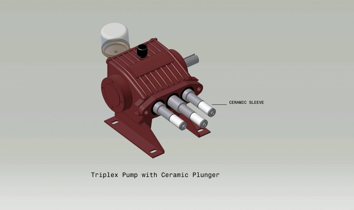
a. All these models use ceramic plungers. Ceramic grade (95% Al2O3) is used for the plungers which offer a surface hardness of around 83RC (against the metallic plungers which offer surface hardness of around 8-10RC). Ceramic has an excellent surface finish and hence a much better coefficient of friction compared to metallic plungers. This material helps in creating a scratch-proof outer surface and hence has a much longer life. Scratch-less plungers obviously increase gland life. Being a non-conductive material, it does not transfer the fluid heat directly to the lubricating oil inside the crankcase. These can be easily replaced without removing the pump from the base plate. Additionally, ceramic is chemically inert towards acids and alkalis which makes it almost corrosion-proof
b. Cup seals are used instead of V-packings. Every plunger is provided with two cup seals, high pressure (primary) and low pressure (secondary). They offer a higher sealing area and hence gland leakages are negligible. They are made from canvas impregnated special rubber compounds to withstand higher temperatures. Cup seals are fitted inside cup seal holders which are tightly held inside the valve box with the help of gland nuts. These seals do not need intermittent/frequent adjustments as in the case of the present V-packings. They offer much better stuffing box sealing and hence atmospheric air does not enter the pump during the suction strokes. This reduces noise, vibrations, and pulsations (can be easily observed from the steady pressure gauge needle)
c. Surface area of the crankcase is increased by providing cooling fins on the crankcase as well as the back cover
d. The new models are provided with bearing covers on both drive end (DE) and non-drive end (NDE) sides. Both the covers are provided with a double oil sealing arrangement by using an O-ring along with an additional plain gasket. The driving end bearing oil seal is fitted inside the bearing cover which offers easy and quick replacement (Model PDH -362). The piston oil seals are fitted inside a separate oil seal holder. This helps in removing/replacing the oil seal without removing the pump from the base plate.
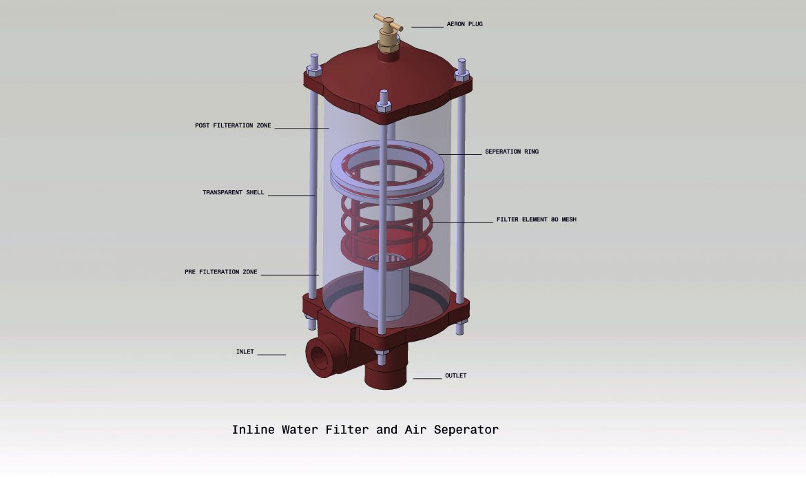
II. A high-temperature inline water filter has been designed as a unique accessory for the new series pumps. Apart from offering a higher filtration area and clear visual signals this also offers two additional facilities. It helps to remove the air bubbles from the suction line which can affect the coil life. It also provides a post-filtration water column which acts as a low-pressure pulsation dampener on the pump suction side. This immensely helps in restricting cavitation as well as liquid separation.
a. Cavitation: In the high-temperature series pumps, we have restricted the plunger diameters to 25mm max. The NPSHR curve for plungers up to 25mm diameter is almost flat (there is no considerable increase in NPSHR even with the increase in pump speed up to 500RPM)
b. Liquid Separation and Flashing: For the high-temperature series, we have restricted the net pump speeds of all the models to well below 500RPM. The maximum plunger diameter of these models is 25mm. This allows the use of present suction and discharge valve assemblies. The spring tension of the valve assemblies for these pumps is slightly modified to achieve optimum performance.
All the present models as well as the high-temperature models are designed for ‘Intermittent Duty’. This means that they are not expected to run for more than 8-10hrs/day. In such a case, a standby pump is highly recommended (that is the reason why the institutions like IBR and API make the standby pumps mandatory on the installations which are expected to offer ‘Continuous Duty’).
C. High-Temperature models (105oC max): PBH-353, PDH-363
These models need the following additional features:
- External cold-water connection for cooling
- Booster pump at the pump inlet in case of the suction tank height is less than 6 meters
As an overview, it would call for a lot of overall awareness to move from 60oC inlet temperature to 70/80oC or 90oC. Proper instrumentation and monitoring both are mandatory. The new mantra is to create the right combination of automation, and clear & simple visual signals for the boiler operator to help him react to any demanding situation.
References
- PUMP HANDBOOK. Igor J. Karassik ,William C. Krutzsch
- MARKS’ STANDARD HANDBOOK FOR MECHANICAL ENGINEERS. Eugene A. Avallone,Theodore Baumeister III
Anand D. Bapat, CEO (Product), DAMPF-KOLBEN ENGG. Corporation, Pune