ABSTRACT
Residual stresses sometimes can severely affect the performance of different components in engineering applications. Some knowledge of residual stress within the materials is necessary to prevent premature failure of engineering material components. The technical aspects of the measurement of residual stresses of welded materials have been discussed in this present study.
1.0 INTRODUCTION
Residual stress in a body is those which are not necessary to maintain equilibrium between the body and its environment [1]. It is a kind of elastic stress that is associated with the elastic strain in the material. It is the result of unnerve elastic deformation and elastic-plastic deformation in the material. This is basically a reflection of the elastic-plastic anisotropy of the material [2]. Residual stresses remain in the material or body after manufacturing and processing in the absence of external processes or thermal gradients [3].
2.0 ORIGIN OF RESIDUAL STRESSES
The origin of residual stresses (RS) is a component that may be classified as
i) mechanical
ii) thermal
iii) chemical [3]
Thermally generated residual stresses are often the consequences of non-uniform heating and cooling operations. This can lead to sincere thermal gradients and the development of large internal stresses [R3]. RS may affect the performance of the component. Tensile residual stresses are generally undesirable as far as structural integrity is concerned [3]. RS can significantly affect the engineering properties of materials and structural components, notably fatigue life, distortion, dimensional stability, and corrosion resistance [4]. Residual stress, therefore, is one of the main factors, determining the engineering properties of materials, parts and welded elements. These factors should be taken into account during the design and manufacturing of different products. A considerable effect is required to develop, efficient and cost-effective methods of residual stress analysis [5].
In this present study, the available technique for measuring residual stress of welded samples has been discussed with their characteristics.
3.0 METHODS FOR MEASUREMENT OF RESIDUAL STRESS
3.1 Neutron diffraction study of residual stress due to welding
Diffraction is the principal Non-Destructive (ND) means of measuring residual stress. Two main ideas are noted, first, if residual stress (strain) is present in a sample, the interplanar spacing is altered relative to the unstressed state, causing shifts in the position of diffraction peaks. Second, given stress so the peak position generally changes with sample orientation. Since engineering materials are polycrystalline, there will be grains oriented differently in any sample orientation for a given peak. Residual stressed strains are measured by systematically changing the sample orientation, observing the shifts in peak position, then converting the shifts first to strain and then to stress, using elasticity theory. The greatest advantage over X-ray is that Neutron penetrates many mm to cm in most engineering materials up to 100 mm in Aluminium and 25 mm in steel. Thus through the thickness, macro residual stain measurements are possible [6]. Measurement of residual stress is possible over a large range of specimen sizes e.g. from 6mm dia. to 600mm dia steel cylinder with girth welds. Neutron diffraction measurements use lattice spacing as a strain gauge, obtained from Bragg Law: nʎ = 2d Sinɵ[7]. ‘ɵ’ is a diffraction angle corresponding to a particular hkl reflecting plane. Any changes in lattice spacing Δd =ʎd – do, where do is the unstrained lattice spacing will result in a change in ʎ or ɵ and a strain Ɛ is given by (d- do)/do. To make measurements it is necessary to precisely position and aligns the sample to be examined in a diffractometer. For the welding sample, because of symmetry, the principle discretion coincides with the normal, transverse and redial directions, so that measurements of strain in these orientations are needed to completely define the stress tensor at a point. With high spatial resolution, Neutron diffraction can provide a complete 3 Dimensional strain map of engineering components. However, compared to the X-ray diffraction method, the relative cost is much higher and availability is also very much lower [3].
3.1.1 Results of a Residual Stress Distribution
The stress distribution of a double V butt welded sample is shown in Figure.1. The normal and transverse components are compressive in the weld zone around the centre line and in the surface of the weld [7]. The welds become tensile with the distance away from the centre line. The transverse stresses become tensile close to the surface in the weld centre zone. The normal component is compressive, falling off with the distance close to the surface. Both of the components become almost zero at about 25 mm from the weld centre. The longitudinal component is tensile around the weld centre with a maximum at the distance of 6 mm away from the weld centre and becomes compressive at the distance away about 40 mm from the centre.
3.2 Residual Stress Measurement In Welded Plate By Ultrasonic Method
One of the promising directions in the development of ND techniques for RS measurement is the application of ultrasound. The principle of ultrasonic (UT) measurement of mechanical stresses is based on the acoustic elastic effect. According to which the velocity of propagations of ultrasonic waves in solid is dependent on mechanical stresses. The relationship between the changes in velocities of longitudinal ultrasonic waves and shear waves under the action of tensile & compressive external loads in steel and aluminium alloys is represented in Figure.2. It is evident from Figure.2 that, the intensity & character of such changes could be different, depending on material properties. When material properties are known, the stress measurements can be done by determining the velocity of propagation in longitudinal and shear polarized ultrasonic waves [8,9]. This technique is very efficient and allows measuring the residual stress on a laboratory scale and in real structures in the field [10, 11].
Different configurations of ultrasonic equipment can be used for residual stress measurements. The UT waves are launched by a transmitting transducer, propagate through a region of the material and are detected by a receiving transducer (Figure. 3). The technique of using the same transducer for excitation and receiving the ultrasonic waves is often called the pulse-echo method (Figure. 3a). This is effective for the analysis of residual stresses in the interior of the material in the configuration (Figure. 3c), the residual stress in a surface/subsurface layer is determined. In the techniques, the velocities of longitudinal ultrasonic waves and shear waves of orthogonal polarities are measured at a considered point to determine the biaxial residual stresses. The mechanical properties of materials are represented by the proportionality coefficients, which can be calculated or determined experimentally under an external loading of a sample of considered material. The equipment for practical application of the ultrasonic technique for residual stress measurement should be of high resolution and computerised.
3.3 Technical Characteristic Of UT Techniques For Measurement Of Residual Stress
The main technical characteristics are summarised below [8]:
- Stress can be measured in material thickness that varies from 2 to 150 mm
- Errors of stress determination: 5-10 MPa
- Errors of residual stress determination: 0.1 σy(y.s) in MPa
- Stress measurement in fasteners (pins): 25-1000 mm long
- Option of using with independent power supply
- It can be used ND measurement of averaged through-thickness, surface residual and applied stresses in samples, welded elements of structures at the site
3.3.1 Results of RS Determination on the welded joint by Ultrasonic method
The measurement of welding residual stress was performed on an 8 mm thick specimen with
longitudinal attachments welded from both sides and a large side weld panel. The plate dimensions were 600 x 700 mm. Stress in direction of longitudinal attachment is denoted by σ33 and stress normal to the direction of longitudinal attachment is denoted as σ22. The Distribution of residual stress in a welded condition along the welded stiffness is presented in Figure. 4. [9]. The result showed that maximum residual stress near the weld (4-5mm away from the weld), acting in the direction of longitudinal attachment and applied load reach loads of 290-320 MPa ( ~YS of material).
3.3.2 Relaxation of Residual stress in a Welded panel
In the process, the ultrasonic gauge when placed as close as possible to the critical weld at a distance of 4.5 mm from the weld. The residual stress at the point was measured before testing and after 1, 2 and 10 cycles of constant amplitude loading between 51 kN and -21 kN. After compilation of the 10th cycle, 2000 cycles of variable amplitude cycle stress were applied to the welded joint panel and residual stress along the welded stiffing in welded panel after 2000 cycles of loading is shown in Figure. 5. It is apparent from the figure that, the Residual stresses after cyclic loading change from tensile to compression in nature up to 30 mm from the weld and thereafter a constant trend of Residual stress is mentioned beyond 30 mm from the weld shown in Figure. 6.
4. SUMMARY
4. SUMMARY
Residual stresses play an important role in the operating performance of materials, parts and structural elements. The developed advanced X-ray diffraction, neutron diffraction and ultrasonic method based on portable instruments with supporting software can be used for non-destructive measurement of applied and residual stresses in laboratory samples and real structural parts in many engineering applications for a wide range of materials.
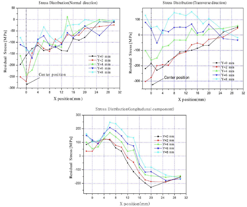
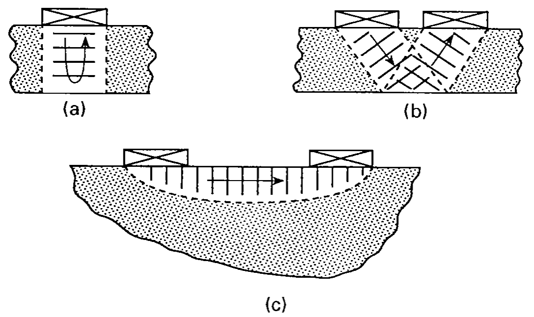
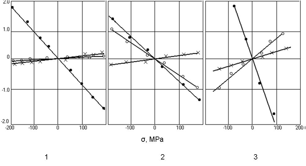
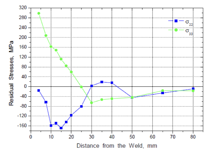
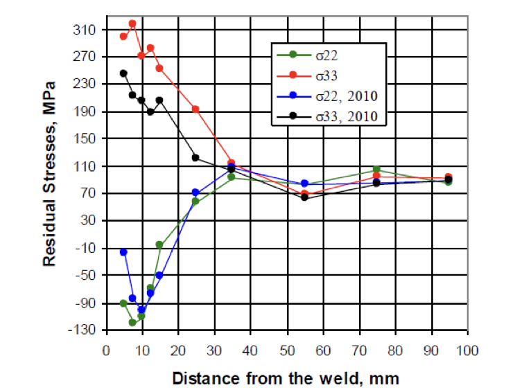
Figure. 5 The distribution of residual stress along the welded stiffener in welded panel before and after 2010 cycles of loading
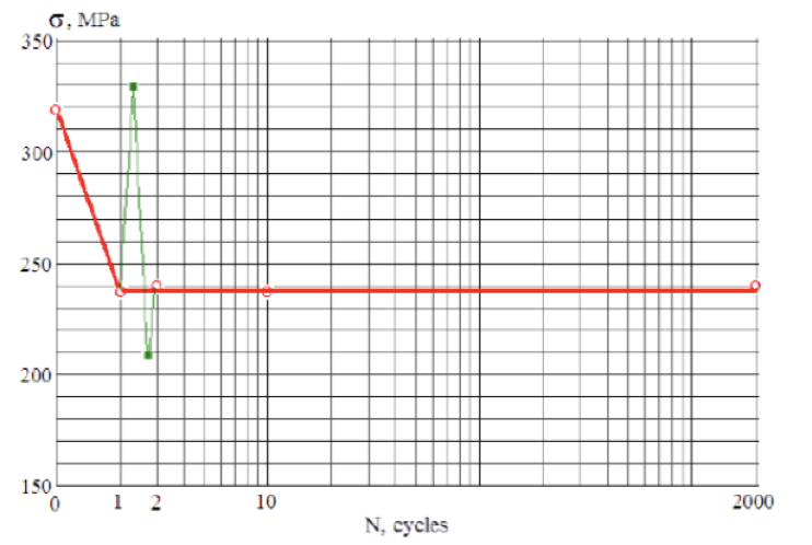
Figure. 6 The relationship between the level of residual stresses and the number of cycles of loading (redline) and max/min stresses during the second cycle of loading (green line)
5. REFERENCES
- Withers P. J. And Bhadeshia H. K. D. H. (2001); Residual Stress Part 1 – Measurement Techniques, Mater. Sci. Technol., 17, P 366 – 375
- Chen Shen, School Of Mechanical, Materials And Mechatronic Engineering, (2013); Low Distortion Welding For Shipbuilding Industry, Master Of Engineering Thesis, University Of Wollongong.
- Kandil, F A, Lord, J D, Fry, A T, Grant And P V (2001); A Review Of Residual Stress Measurement Methods – A Guide To Technique Selection. Npl Report Match (A)04, P 1-42
- Jian Lu (Editor), (2005); Handbook On Residual Stress, Second Edition, Soc. For Exper. Mechanics, Vol. 1 P 274-285
- Lu, J., James, M., Roy, G., (Ed.), Handbook Of Measurements Of Residual Stress, Usa, Fairmont Press, Inc., 1996.
- Hutchings, M.T., Krawitz And A. D.(1991); Measurement Of Residual And Applied Stress Using Neutron Diffraction, Nato Asi Series E, Vol. 216, P. 285
- Park M J, Yang H N, Jang D Y, Kim J S And Jin T E (2004); Residual Stress Measurement On Welded Specimen By Neutron Diffraction J. Materials Processing Technol. 155-156 1171–77
- Kudryavtsev Y. (2013); Ultrasonic Measurement Of Residual Stresses In Welded Specimens And Structures. Proceedings Of The Asme 2013 Pressure Vessels And Piping Conference Pvp 2013, July 14-18, Paris, France, P 1-6.
- Kudryavtsev Y. And Kleiman J. (2010); Measurement Of Residual Stresses In Welded Elements And Structures By Ultrasonic Method. International Institute Of Welding. Document Xiii-2339-10.
- Kudryavtsev Y. (2008); Residual Stress. Springer Handbook On Experimental Solid Mechanics. Springer – Sem. P. 371-387.
- Polezhayeva H., Kang J., Lee J., Yang Y. And Kudryavtsev Y.(2010); A Study On Residual Stress Distribution And Relaxation In Welded Components. Proceedings Of The 20th International Offshore (Ocean) And Polar Engineering Conference Isope-2010, Beijing, China, June 20-26.
Dr P. Kanjilal, Director, National Test House (NTH-WR) with U. Thanu, Director General (NTH) R. N. Lokesh, Scientific Officer-Mech (NTH-WR) and R. Kumar, Scientist SB-NDT (NTH-ER)