The efficiency of conventional boilers is strictly based on the steam temperature and pressure. Since the energy crisis, there have been efforts worldwide to reduce the fuel consumption per MW. The need to reduce carbon dioxide, nitrogen oxides, sulphur oxides has provided further impetus to improve efficiency. In order to achieve this, the development of new boiler technologies- supercritical and ultra-supercritical is the prime requirement. Steam cycles for supercritical applications operate above critical points; these are thus characterised by features that take full advantage of the advanced parameters like the higher expansion of the turbine, more stages of feed heating & higher input levels to boilers; contributing to higher system efficiency. All the components of the cycle are optimally designed to take advantage of these elevated parameters. All of these contribute to lower land and water use, less consumption of coal reduced waste and emissions.
A supercritical steam generator is a type of boiler that operates at supercritical pressure, frequently used in the production of electric power. In contrast to a subcritical boiler in which bubbles can form, a supercritical steam generator operates at pressures above the critical pressure – 22 Mega Pascals (3,200 psi).
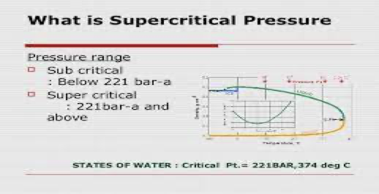
The term ‘supercritical’ in supercritical boilers refers to the pressures above the critical point of water that the boiler is being operated at. The critical point of water is at 647 K temperature and 221 bar (22.1 MPa) pressure.
Rather than boiling water to produce steam and then using that steam to run a plant’s turbine, a supercritical boiler operates at such high pressure (3,208 psi/221.2 bar or above) that the fluid matrix in it ceases to be a liquid or gas.
Supercritical Technology
Supercritical Technology
‘Supercritical’ is a thermodynamic expression describing the state of a substance where there is no clear distinction between the liquid and the gaseous phase (i.e. they are a homogenous fluid). The water reaches this state at a pressure above 22.1 Mega Pascals (MPa). Up to an operating pressure of around 19 MPa in the evaporator part of the boiler, the cycle is subcritical. This means, that there is a non-homogeneous mixture of water and steam in the evaporator part of the boiler. In this case, a drum-type boiler is used because the steam needs to be separated from water in the drum of the boiler before it is superheated and led into the turbine. Above an operating pressure of 22.1 MPa in the evaporator part of the boiler, the cycle is supercritical. The cycle medium is a single-phase fluid with homogeneous properties and there is no need to separate steam from the water in a drum. Once-through boilers are therefore used in supercritical cycles.
Parameters to define subcritical, supercritical and ultra supercritical-
| Sr. No. | Technology | Pressure ( MPa) | Temperature (ºC) | Efficiency (%) |
| 1. | Subcritical | up to 22.1 | 540- 565 | 36-37 |
| 2. | Supercritical | 24.2-27.2 | 565-593 | 40-42 |
| 3. | Ultra supercritical | >27.2 | > 593 | 48-55 |
TYPES OF SUPERCRITICAL BOILERS
Spiral Wound Universal Pressure (SWUP) Boiler
Supercritical boiler that is usually applied to 400 MW systems or larger; the design features a water-cooled dry-bottom furnace, superheater, reheater, economizer, and air heater components. It is designed for both baseload and full boiler variable pressure load cycling operation as well as on/off cycling operation.
Universal Pressure (UP) Boiler
A once-through boiler for supercritical applications, usually applied to systems with a capacity of 400 MW or larger; the design features a water-cooled dry bottom furnace, superheater, reheater, economizer, and air heater components designed for variable superheater pressure load cycling and baseload operation.
Vertical Tube Universal Pressure (VTUP) Boiler
A once-through boiler for supercritical applications, usually applied to systems with a capacity of 400 MW or larger. It is designed for both baseload and full boiler variable pressure load cycling operation as well as on/off cycling operation.
There are no operational limitations due to once-through boilers compared to drum-type boilers. In fact, once-through boilers are better suited for frequent load variations than drum-type boilers, since the drum is a component with a high wall thickness, requiring controlled heating. This limits the load change rate to 3% per minute, while once-through boilers can step up the load by 5% per minute. This makes once-through boilers more suitable for a fast start-up as well as for transient conditions.
Current designs of supercritical plants have installation costs that are only 2% higher than those of subcritical plants. Fuel costs are considerably lower due to the increased efficiency and operating costs are at the same level as subcritical plants. Specific installation cost i.e. the cost per megawatt (MW) decreases with increased plant size.
Comparison of subcritical and supercritical
| Sr No. | Description | Supercritical | Subcritical |
| 01. | Circulation Ratio | 1 | Once-thru=1 Assisted Circulation=3-4 Natural circulation= 7-8 |
| 02. | Feed water Flow Control | Water to Fuel Ratio (7:1) -OHDR(22-35 OC) -Load Demand | Three Element Control -Feed Water Flow -MS Flow -Drum Level |
| 03. | Latent Heat Addition | Nil | Heat addition more |
| 04. | Specific Enthalpy | Low | More |
| 05. | Sp. Coal Consumption | Low ( approx. 4% less than subcritical) | High |
| 06. | Air Flow & Dry Flu Gas Loss | Low | High |
| 07. | Coal and Ash handling | Low | High |
| 08. | Pollution | Low | High |
| 09. | Auxiliary Power Consumption | Low (6%) | More (7-8%) |
| 10. | Overall Efficiency | High (40-42%) | Low (36-37%) |
| 11. | Total Heating Surface Required | Low (84439m2) | High (71582m2) |
| 12. | Tube Diameter | Low | High |
| 13. | Material Requirement ( Tonnes) | Low 7502 MT | High 9200 MT |
| 14. | Start Up Time | Less | More |
| 15. | Blow Down Loss | Nil | More |
| 16. | Water Consumption | Less | More |
| 17. | Cost Of Generation | Less | More |
Design features of Super Critical Boilers
Sliding Pressure Operation
Sliding Pressure implies the variable pressure required at the turbine inlet based on load and steam flow rate. Again, the sliding pressure can be classified as pure sliding pressure, modified sliding pressure etc. The basic characteristic of a simple, rotating turbine is to require less pressure as load and flow rate are reduced, and if the main steam pressure is limited to only that required for each load, this mode is referred to as pure sliding pressure.
However, when we speak generally of ‘sliding pressure’ we often mean ‘modified sliding pressure’.
This mode has a limited amount of pressure throttling to provide a modest amount of fast-response load reserve. The modified sliding pressure operation combines the advantages of constant-pressure operation with those of the sliding pressure mode. The ability to activate the storage capacity of the boiler by opening the throttle valves is combined with the advantages of low lifetime consumption of the plant and high part-load efficiency.
Water wall arrangements
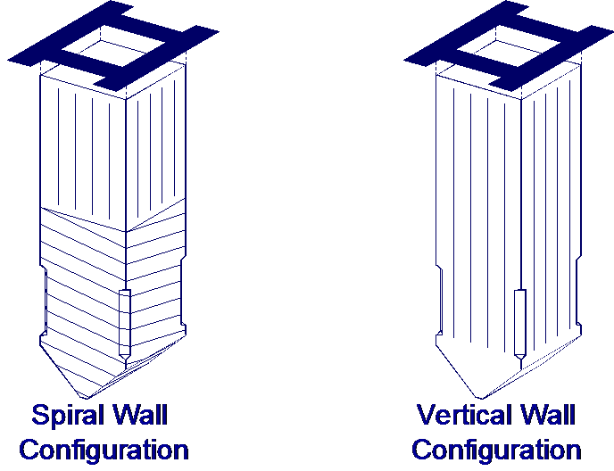
Spiral Waterwall Tubes
Among the heat-absorbing surfaces, the furnace walls are exposed to the highest heat flux. This is because of the intense radiant heat from the fireball.
Currently, two design variants are used for once-through units: the spiral furnace tube arrangement and the vertical tube arrangement. The design choice is governed by furnace size and customer preference–both variants have advantages, depending on project drivers.
Spiral Configuration
1) Benefits result from averaging lateral heat absorption variation (each
tube forms a part of each furnace wall).
2) Simplified inlet header arrangement.
3) A large number of operating units
4) Use of smooth bore tubing throughout the entire furnace wall system
5) No individual tube orifices.
For any given furnace size, the spiral wall unit (in which the tube is ‘wrapped’ around the unit) has fewer tubes than the vertical wall unit.
Vertical Configuration
The vertical water wall design uses internal ribbing in the tubes to improve heat transfer. The vertical wall option is suitable for larger units where lower perimeter-to-furnace plan area ratios result in higher fluid flow per tube. Refer the following figure. The vertically oriented tubes are self-supporting within the wall, allowing a simpler support system. The relatively simple vertical wall furnace has certain significant advantages like
1) Simpler wind box openings.
2) Simpler furnace water wall support system.
3) Elimination of intermediate furnace wall transition header.
4) Less costly to construct.
5) Easier to identify and repair tube leaks.
6) Lower water wall system pressure drop thereby reducing required feed pump power.
Startup and low load re-circulation system
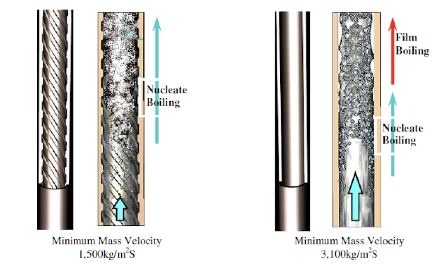
One of the critical parameters of a once-through system is the proper selection of minimum acceptable once-through flow in the evaporator tubes.
Below a particular load, the water wall flow is kept constant in order to ensure flow, is high enough to cool the tubes. This load is typically 30-40% of BMCR and below this load, the boiler will operate under the low load re-circulation system.
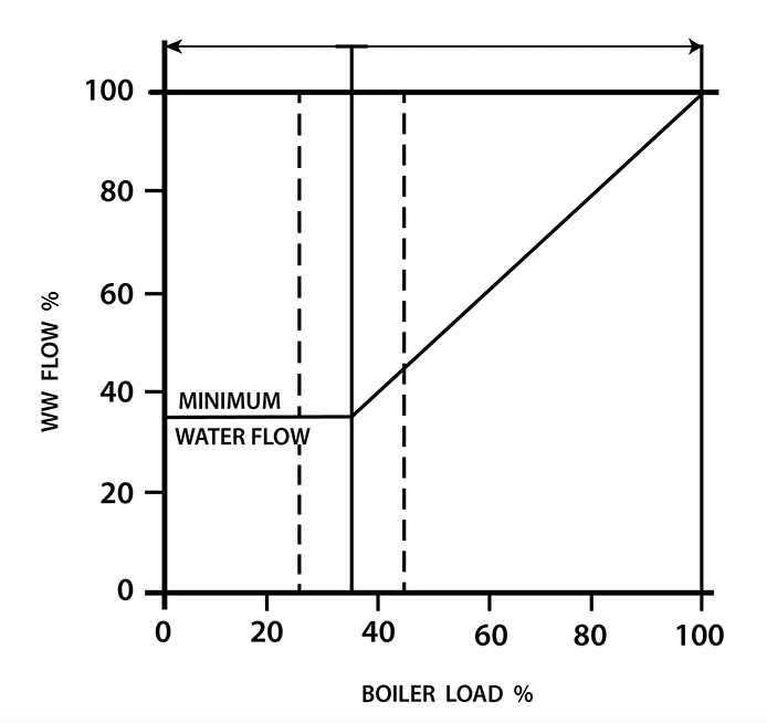
At low loads where the water flow is to be kept constant, a water-steam separator and a drain water return system are required. The water separator consists of one or more vertical vessels with tangential inlets. The separator is in a wet condition when operating under the low load circulation range. In the once-through mode, the separator runs dry.
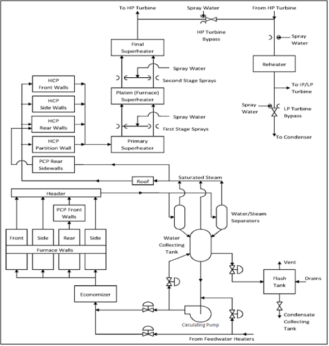
Steam Separator
Generally a steam separator and a separator drain tank were installed to separate the steam and the water at the furnace outlet during a low-load recirculation operation. This design is different from that of a conventional NC boiler, for which a steam drum is installed to separate the water from the steam under all operating loads. The steam drum is designed to have sufficient water storage capacity, and usually contains complicated internal parts, such as steam cyclones, scrubbers, internal feed pipes, and baffles. Because of the complex internals, steam drums require a large amount of maintenance work during outage periods. However, the steam separator design is simple in configuration and has no internals, therefore significantly less maintenance work is required.
Boiler Startup Systems
The startup system in supercritical boilers are used to protect super-heaters from water carry-over by separating water from steam and re-circulating it through the evaporator surfaces during start-up, low load operation and shutdown of the boiler. The required water flow rate through the evaporator tubes is therefore maintained greater than the evaporation rate to protect them against overheating.
The startup system equipment consists of two steam-water separators, a water collection tank, a boiler circulating pump and the associated piping and control valves to return the fluid from the water collection tank to the economizer inlet.
During startup, the unit is operated much like a drum boiler where water is recirculated to maintain a minimum flow through the furnace equivalent to 30% of full load flow. The system is similar to a pumped circulation drum boiler with the steam water separators and the water collection tank functioning like the steam drum. The water flowing through the furnace is a combination of water from the water collection tank and boiler feedwater. The boiler feed pump controls the total flow through the furnace so the minimum required mass flow is maintained. Steam generated through the furnace circuits is separated from the water in the vertical separator, routed to the superheater and then to either the steam turbine or the turbine’s bypass system. The water from the vertical separator is returned to the water collection tank and then to the circulating pump. The 381 valve, located at the discharge of the circulating pump, controls the flow proportionately to tank level to maintain the water inventory in the collection tank. Water is also recirculated from the pump discharge to the collecting tank to ensure that the minimum flow required through the pump is maintained.
Above the minimum boiler load, the unit switches to a once-through operation. The circulating pump is taken out of service but is kept pressurized. A small flow of feedwater from the economizer outlet is routed to the circulating pump inlet and back to the separator to maintain the components in the ready state for use during the shutdown.
From the following figure, we can understand the complete system of the startup of the supercritical boiler. If we can see the startup thoroughly, we will find that starting procedure of a supercritical boiler is similar to that of a subcritical boiler.
SCHEMATIC DIAGRAM OF SUPERCRITICAL BOILER
Sanjay Gaikwad, Consultant, Boilers & heaters


Dilip Mishra
October 23, 2023 at 12:11 pmIts very illustrative on Critical boiler operation is concern and learning too.