The following are widely used welding processes:
- MIG: Gas Metal Arc Welding (GMAW)
- TIG: Gas Tungsten Arc Welding (GTAW)
- Stick: Shielded Metal Arc Welding (SMAW)
- Flux-cored: Flux-cored Arc Welding (FCAW)
- Plasma Arc welding
MIG – GAS METAL ARC WELDING (GMAW)
MIG welding is used in the auto industry for repairing vehicle exhausts and is also used in creating homes and buildings. It is one of the most common types of welding. This is a type of arc welding that uses a continuous wire called an electrode. You will also use a shielding gas that travels through the welding gun and protects against contamination.
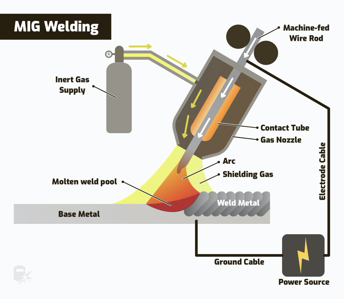
Image courtesy: https://weldguru.com/welding-processes/
TIG – GAS TUNGSTEN ARC WELDING (GTAW)
TIG welding also uses electric arcs like MIG. When working with TIG welding, you use an electrode made of tungsten. Tungsten is one of the toughest metal materials. It will not dissolve or burn off. Welding can be done through a process known as fusion which is using or not using a filler metal. TIG also uses an external gas supply, such as Argon or Helium.
Aerospace and auto also use TIG welding as well as other industrial markets. Two hands are needed for TIG welding. One hand feeds the rod whilst the other holds a TIG torch. This torch creates the heat and arc, which are used to weld most conventional metals, including aluminium, steel, nickel alloys, copper alloys, cobalt and titanium.TIG welders can be used to weld steel, stainless steel, Chromoly, aluminium, nickel alloys, magnesium, copper, brass, bronze, and even gold.
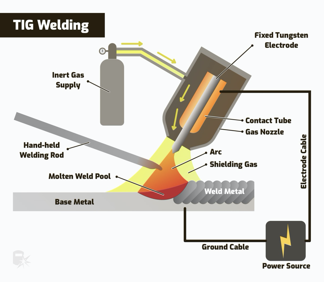
Image courtesy: https://weldguru.com/welding-processes/
STICK – SHIELDED METAL ARC WELDING (SMAW)
One big positive about Stick welding is that it’s portable. Stick welding is used in construction, maintenance and repair, underwater pipelines, and industrial fabrication. For this type of welding, you will use shielded metal art welding or more commonly known as Stick welding. You will use a consumable and protected electrode, or stick. The stick softens and combines metals by heating with an arc between a covered metal electrode and the base metal workpiece. As the stick melts, its protective cover also melts and shields the weld area from oxygen and other gases that may be in the air.
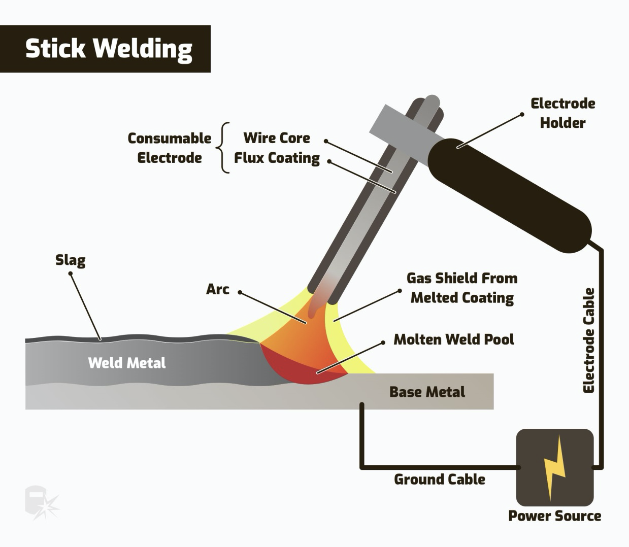
Image courtesy: https://weldguru.com/welding-processes/
FLUX-CORED – FLUX-CORED ARC WELDING (FCAW)
Flux-cored arc welding is similar to MIG welding because both use continuous wire and power supplies. You will combine a continuous electrode with a base metal. The electrode is a hollow tube filled with flux that is fed through the weld gun and into the weld pool. When welding outdoors, a flux shield offers protection against weather elements. This type of welding is used for welding thicker metals and is used in machining industries.
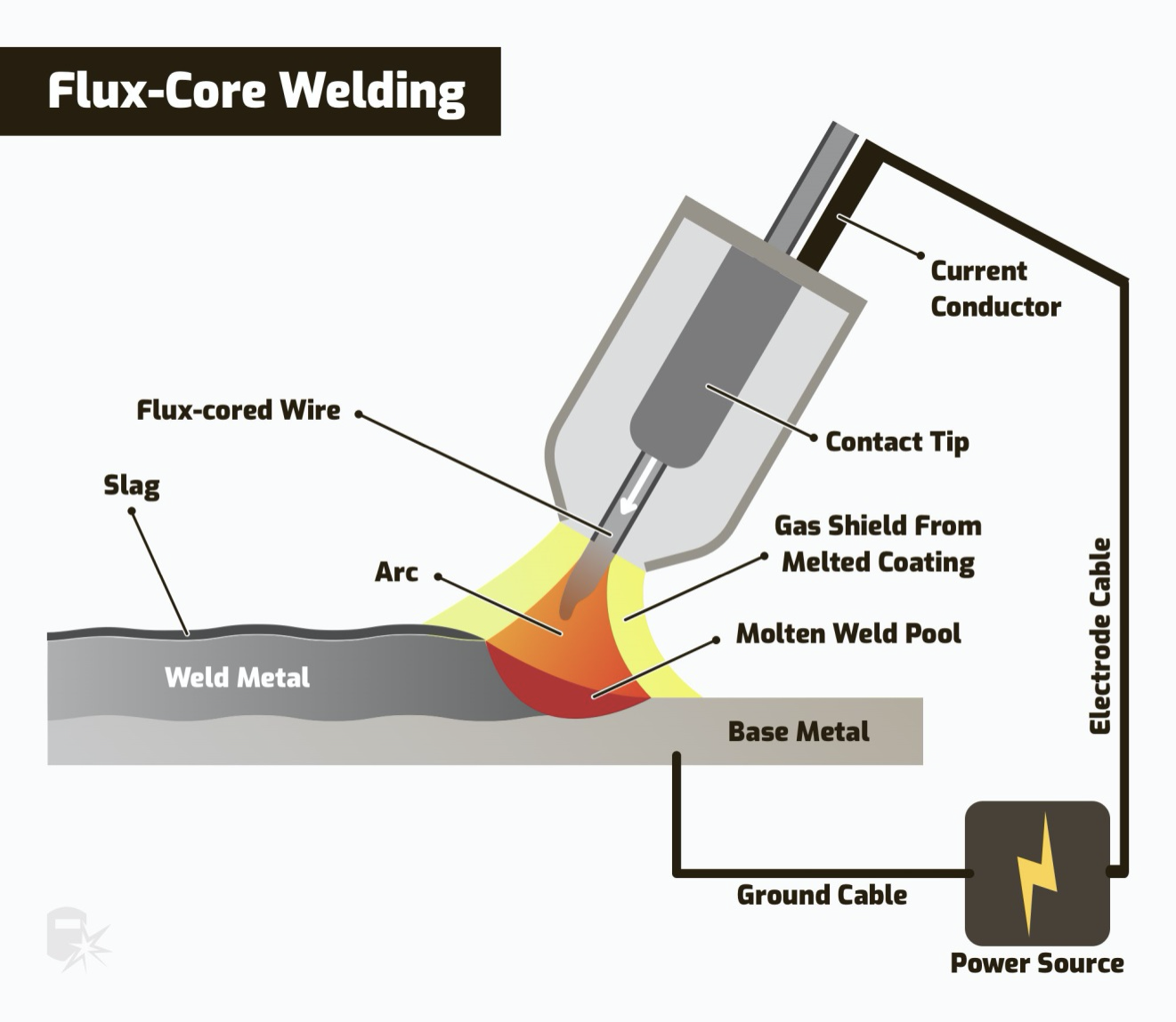
Image courtesy: https://weldguru.com/welding-processes/
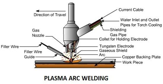
PLASMA ARC WELDING
Plasma arc welding is a precision technique and is commonly used in aerospace applications where metal thickness is 0.015 inch. One example of such an application would be on an engine blade or an air seal. Plasma arc welding is very similar in technique to TIG welding, but the electrode is recessed and the ionizing gases inside the arc are used to create heat.
The normal combination of gases is argon for the plasma gas, with argon plus 2-5% hydrogen for the shielding gas. Helium can be used for plasma gas but because it is hotter this reduces the current rating of the nozzle.
Plasma welding is very similar to TIG as the arc is formed between a pointed tungsten electrode and the workpiece. However, by positioning the electrode within the body of the torch, the plasma arc can be separated from the shielding gas envelope. Plasma is then forced through a fine-bore copper nozzle which constricts the arc. Three operating modes can be produced by varying bore diameter and plasma gas flow rate:
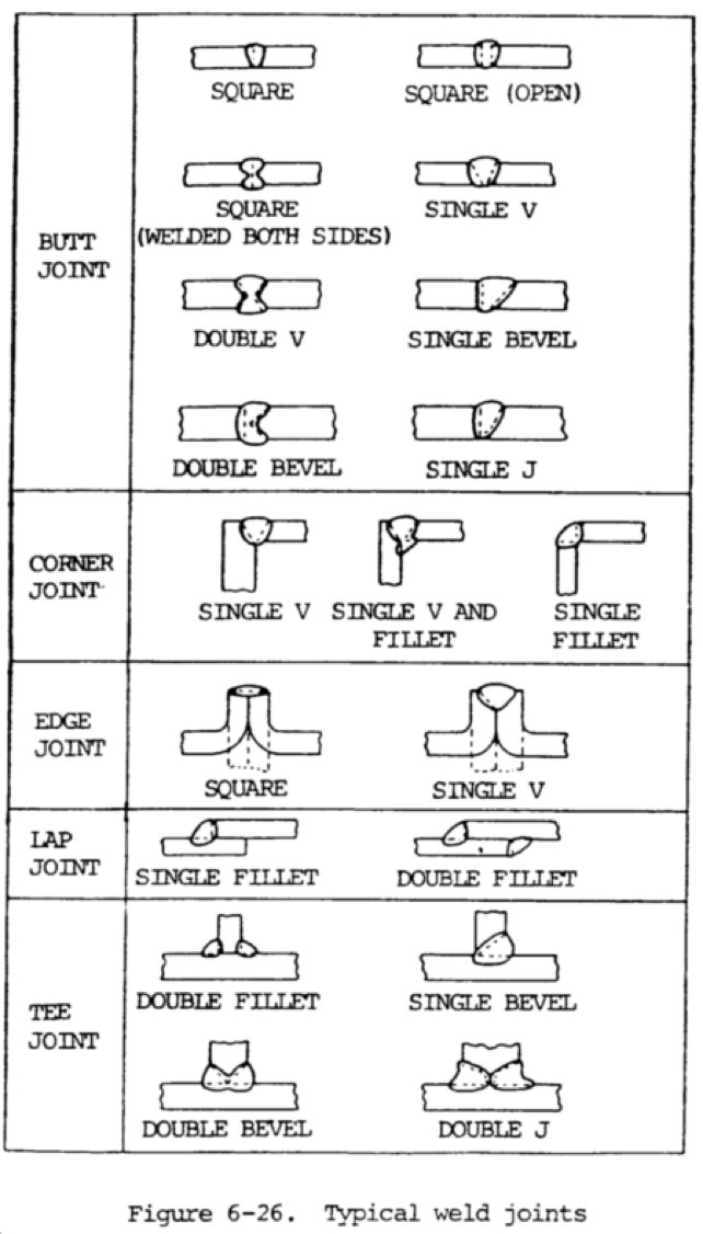
TYPE OF WELD JOINTS
BASIC WELDING SYMBOLS
The weld defect acceptance criteria as per ASME Section VIII Div 1, which is one of the most widely used standards for acceptance criteria for weld defects.
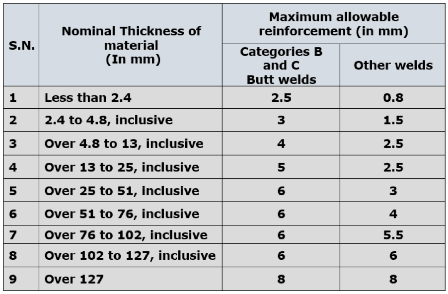
1. Acceptance criteria for Visual Inspection
2. Acceptance criteria for Radiography Test (RT)
3. Acceptance criteria for Ultrasonic Test (UT)
4. Acceptance criteria for Liquid Penetrant Test (LPT/LPI/DPT)
5. Acceptance criteria for Magnetic Particle Test (MPI/MPT/MT)
The surface shall be free of any visible laminations, spalling, or cracks. Cracks in tubes shall not be repaired and shall be considered cause for rejection.
For tubes, the depth of scratch shall not exceed 1/32 inches (0.8 mm). For all other materials, the scratch depth shall not exceed 1/8 inches (3 mm).
The reduction in thickness shall not exceed 1mm (1/32 inches) or 10% of material nominal thickness whichever is less, provided that the material of the adjoining surfaces is below the design thickness at any point.
Acceptance criteria for Radiography Test (RT)
(Refer: UW-51: Sub Para b (Page 148 and 149) and Mandatory Appendix 4 (Page 400 and Page 403) of ASME BPVC Section VIII Div 1, 2017 Edition)
Following terminologies have been used to explain the acceptance/rejection criteria for Radiography Test (RT):
Linear Indication: Any indication with a length greater than three times the width. Linear indications are mainly cracks, lack of penetration, lack of fusion, and elongated slag inclusions.
Rounded Indication: Any indication with a length equal to or less than three times the width. A rounded indication may be circular, elliptical, conical, or irregular in shape and may have tails too. While determining the size of an indication, the tail shall also be included. Rounded indications may appear on radiographs from any imperfection in the weld, such as porosity, slag, or tungsten.
Acceptance criteria for Linear Indication (UW – 5)
- Any crack, lack of penetration, and lack of fusion shall not be accepted
2. Any other elongated indication shall be considered unacceptable, which has a length greater than;
- 6 mm (1/4 inches) for T up to 19 mm (3/4 inches)
- T/3 for T greater than or equal to 19 mm (3/4 inches) and less than or equal to 57 mm (2-1/4 inches) i.e. 19 mm ≤ T ≤ 57 mm
- 19 mm (3/4 inches) for T greater than 57 mm (2-1/4 inches)
(Where ‘T’ – Thickness of the weld metal excluding any allowable reinforcement)
3. Any group of indications (inline) with an aggregate length of more than T (within a length of 12T) shall be considered unacceptable except when the distance between the successive discontinuities exceeds 6L.
(Where ‘L’ is the length of the longest imperfection in the group)
Acceptance Criteria for Rounded Indication
According to this appendix, those rounded indications which exceed the following dimensions shall be considered relevant:
- T/10 for T less than 3 mm (1/8 inches)
- 0.5 mm (1/64 inches) for T from 3 mm to 6 mm (1/8 inches to 1/4 inches), inclusive
- 1.0 mm (1/32 inches) for t greater than 6 mm to 50 mm (1/4 in. to 2 inches), inclusive
- 1.5 mm (1/16 inches) for T greater than 50 mm (2 inches)
Acceptance criteria for Ultrasonic Test (UT)
(a) Indications characterized as cracks, lack of fusion, or incomplete penetration are unacceptable regardless of length
(b) Other imperfections are unacceptable if the indications exceed the reference level amplitude and have lengths that exceed:
- 6 mm (1/4 inches) for T up to 19 mm (3/4 inches)
- T/3 for T from 19 mm to 57 mm (3/4 in. to 21/4 inches)
- 19 mm (3/4 inches) for T over 57 mm (21/4 inches)
Where T is the thickness of the weld excluding any allowable reinforcement. For a butt weld joining two members having different thicknesses at the weld, T is the thinner of these two thicknesses. If a full penetration weld includes a fillet weld, the thickness of the throat of the fillet.
Acceptance Criteria for Liquid Penetrant Test
The following terminologies have been used to explain the acceptance/rejection criteria for Liquid Penetrant Examination (PT).
Relevant Indications: Indications with major dimensions greater than 1.5 mm (1/16 inches) shall be considered relevant.
Linear Indication: Any indication with a length greater than three times the width.
Rounded Indication: Any indication with a length equal to or less than three times the width. A rounded indication may be of circular or elliptical shape.
Acceptance Criteria for Liquid Penetrant Examination
All surfaces to be examined shall be free of:
(a) Relevant linear indications shall be rejected
(b) Relevant rounded indications greater than 5 mm (3/16 inches) shall be rejected
(c) Four or more relevant rounded indications in a line separated by 1.5 mm (1/16 inches) or less (edge to edge)
Acceptance criteria for Magnetic Particle Test (MT)
The following terminologies have been used to explain the acceptance/rejection criteria for Magnetic Particle Test (PT).
Relevant Indications: Indications with major dimensions greater than 1.5 mm (1/16 inches) shall be considered relevant.
Linear Indication: Any indication with a length greater than three times the width.
Rounded Indication: Any indication with a length equal to or less than three times the width. A rounded indication may be of circular or elliptical shape.
Acceptance Criteria for Magnetic Particle Examination
All surfaces to be examined shall be free of:
(a) Relevant linear indications shall be rejected
(b) Relevant rounded indications greater than 5 mm (3/16 inches) shall be rejected
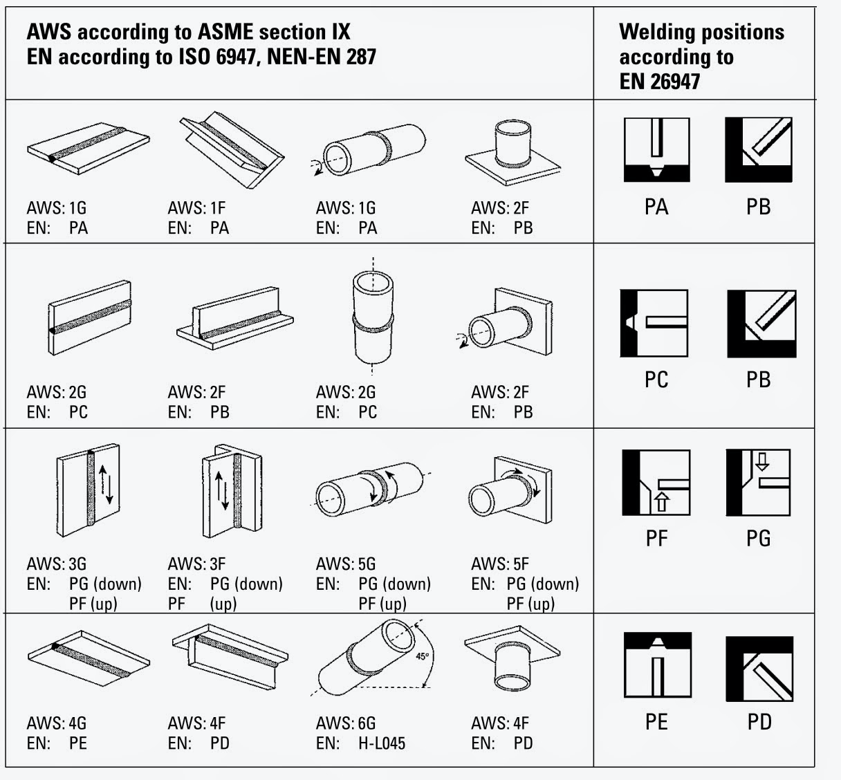
WELDING POSITIONS AS PER AWS – ASME SECT IX
How to calculate heat input
Heat input is a critical parameter for arc welding processes and it must be controlled to ensure sound weld quality.
Heat input may be defined as “The amount of electrical energy that is supplied to a weld during the welding process”.
How to calculate Heat input?
There are several ways of calculating the heat input. We shall discuss the two most common methods of calculating the heat input.
A. The American system [given in ASME BPVC Section IX – QW 409.1 (a) and various AWS standards]:
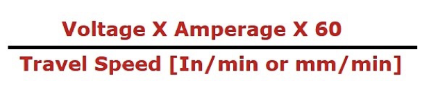
- Heat input is expressed in J/In (Joule/Inch) or J/mm (Joule/mm)
- Voltage is expressed in Volts
- Travel speed is expressed in In/min or mm/min
The unit for heat input obtained by this formula shall be either in J/In or J/mm. To get the results in KJ/in or KJ/mm, divide the result by 1000.
Example 1: If a welder takes 2 minutes to complete an 18 inches long weld. He keeps the voltage at 24 volts and the current at 120 amps. What is your heat input?
Answer:
Travel Speed = Length of Weld/Time to weld = 18 inches/2 minutes = 9 inches/min
Voltage = 24 volts
Current = 120 amps
Heat Input = (24 X 120 X 60)/ 9 = 19200 J/in
= 19.2 KJ/in (Divided by 1000 to obtain the result in KJ/in.)
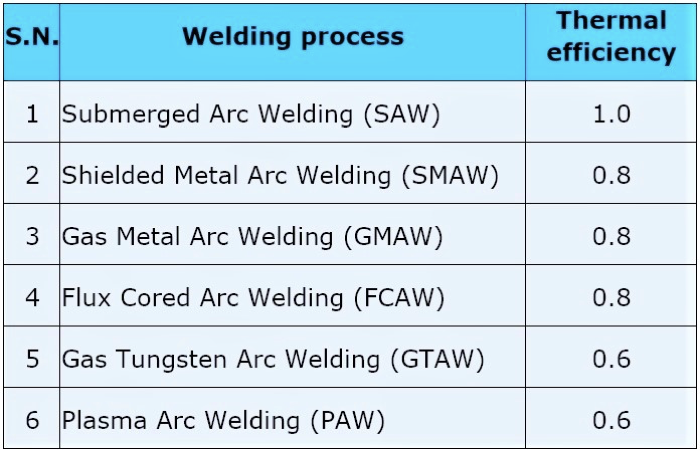
B. European system (given in EN ISO 1011-1 and PD ISO/TR 18491)
An additional parameter of Thermal efficiency (process efficiency or arc efficiency) is used while calculating heat input as per European standards.
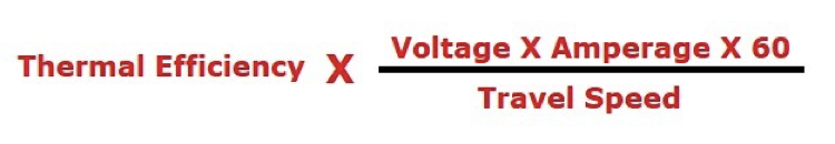
Value of thermal efficiency is different for different arc welding processes, see table
Table
Why Heat input is so important?
Heat input affects the cooling rates in welds and thereby it affects the microstructure of the weld metal and that of the Heat-Affected Zone (HAZ). A change in microstructure directly affects the mechanical properties of weld metal and Heat-Affected Zone (HAZ). Therefore, it’s very important to control the heat input to achieve a sound microstructure and a good quality weld.
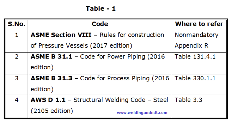
Preheating – How, When and Why
Heating the base metal to a specific desired temperature before welding is called preheating. The temperature at which the base metal is heated is called the preheat temperature. Preheat temperature can be determined by the applicable code. Please see below in table 1 to know how to find the preheat temperature in the respective code:
Why preheating is required?
Preheating is carried out for the following reasons;
In absence of code, the following factors shall be considered for determining the preheat temperature; these are:
- Base metal thickness
- Surrounding temperature
- Base metal composition
- Hydrogen content of the electrode
- Operational requirements
However, in general, preheat is required above 25 mm thickness, but other factors shall always be considered before determining the preheat temperature.
- It slows down the cooling rate of weld metal, HAZ (heat affected zone) and adjacent base metals, which yields a good microstructure to the metal, prevents martensite formation at the microstructural level and prevents from cracking of the weld metal and HAZ
- Preheating removes the diffusible Hydrogen from the base metal and hence prevents the chances of Hydrogen induced cracking (HIC)
- It helps in reducing the expansion and contraction rate
- It burns the unwanted material or impurities (if any) present on the joint surface
- Preheating also helps in achieving better mechanical properties such as notch toughness
Oxy-fuel heating torches, Induction heaters, Infrared radiant pane heaters and electrical heaters are commonly used for preheating a joint. It is recommended to preheat the joint from the back side (another side), to ensure that the entire volume of metal, surrounding the joint, has been heated.
Digital infrared pyrometers (Figure 1) or thermal chalks (Figure 2) can be used for checking the temperature of the preheated item.
Welding Procedure Specification (WPS)
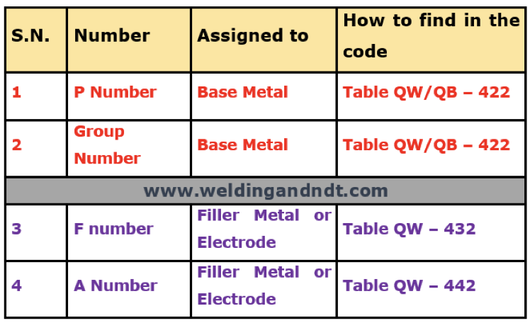
ASME Boiler and pressure vessel code (BPVC) has assigned certain numbers to base metals (to be welded) as well as to filler metals (electrodes).
For base metals, ASME has assigned two number systems, these are;
- P Numbers
- Group Numbers
For filler metals, the number system which is assigned, are as follows;
- F Number
- A Number
These numbers can be found in ASME BPVC Section IX, please see Table–1 for details;
Table – 1
BASE METAL GROUPING:
The main purpose of assigning this number system is to reduce the number of Procedure Qualification Records (PQR). Conducting a procedure qualification requires a lot of time and money due to the following procedural requirements;
- Preparation of test coupon
- welding of test coupons and
- sending it to a lab for destructive test
Hence, to reduce these costly and time-consuming activities, ASME has done groupings of base metals and has assigned certain P numbers to each group of metals. This grouping of base metals has been done on the basis of the following parameters;
- Material composition
- Weldability Mechanical property
Though all materials of the same ‘P’ number don’t exhibit the same properties, after considering the above-mentioned parameters, ASME has done this logical grouping.
Why this grouping is required?
Suppose, if we change the base metal from an existing qualified WPS and if the new base metal falls in the same ‘P’ number then the re-qualification of the existing WPS is not required, it means no need for a new PQR.
But this doesn’t mean that one can easily substitute the base material, from existing WPS, of the same ‘P’ number at any time. Whenever there is a change in the base material from existing WPS, the compatibility shall be considered with regard to the following factors;
- Metallurgical property
- Mechanical property
- Design considerations
- Service requirements
- Heat treatment
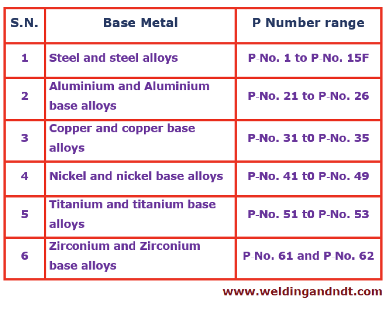
Table–2 shows the assignment groups for various metals and their alloys
Table – 2
Group numbers are subsets of ‘P’ numbers and are assigned to ferrous-based metals. Group numbers are assigned only to those materials which require toughness testing for the qualification of their WPS.
We will take an example of SA516 Gr 65 from table QW/QB-422 (Page – 118 of ASME Section IX, 2017 edition), we can find out the following values;
Base material – SA516 Gr 65
- Tensile strength (min.) – 65 Ksi (or 450 Mpa)
- P-No. – 1
- Group number – 1
- Nominal composition – C-Mn-Si
- Typical product form – Plate
S Numbers were assigned to those materials which were acceptable for use by the ASME B31 Code for Pressure Piping, or by selected Boiler and Pressure Vessel Code Cases, but were not included in section II of ASME Boiler and Pressure Vessel (BPVC). Base metals that were previously assigned ‘S’ Numbers were reassigned to the corresponding P Numbers or P Numbers and Group Numbers.
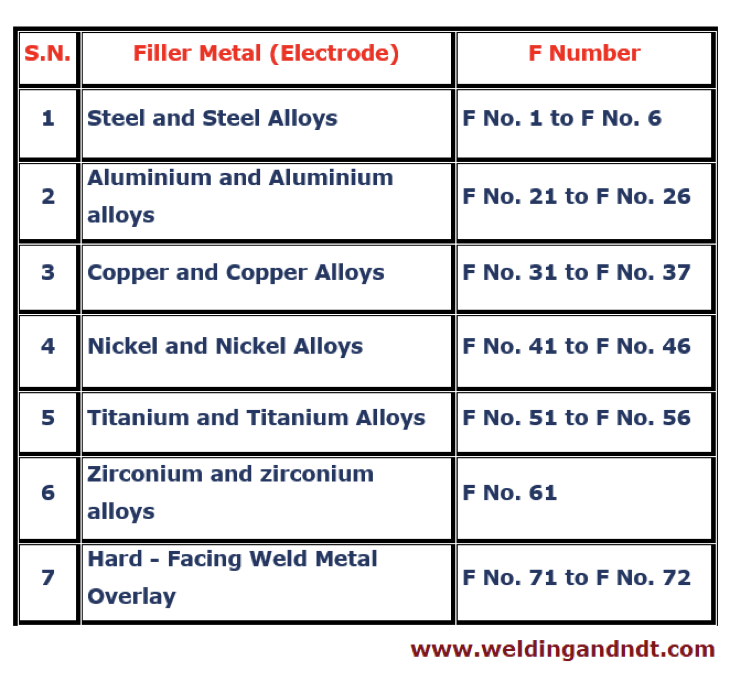
FILLER METAL (ELECTRODE/WELDING ROD) GROUPING:
The F Number: F number grouping (for filler metals) is done to reduce the number of welding procedure specifications (WPS) and welder performance qualifications. The basis for F number grouping is usability characteristics. The usability characteristics fundamentally determine the ability of a welder to produce sound welds with a given filler metal. Hence it is assumed if a welder can make a satisfactory weld with particular filler metal, he will be able to weld with all the filler metals belonging to that particular ‘F-number.’
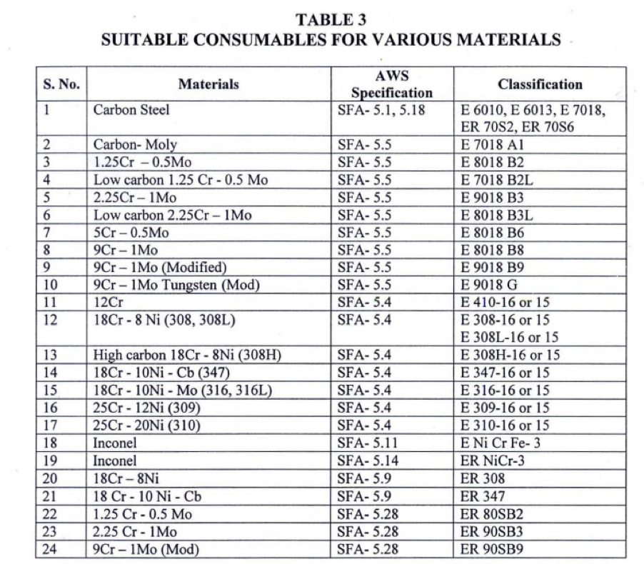
Table 3 shows a brief summary of ‘F’ and filler metals (according to ASME BPVC, Table: QW-432).
Table – 3
The ‘F’ number grouping doesn’t imply that one can easily substitute the filler metal (electrode/welding rod), from existing WPS, of the same F-number at any time. Whenever there is a change in the filler metal (electrode/welding rod) from existing WPS, the compatibility shall be considered with regards to the following factors;
- Metallurgical property
- Mechanical property
- Design considerations
- Service requirements
- Heat treatment
The A Number: Another type of grouping for filler metal or welding rod is the ‘A’ Number. ‘A’ number grouping has been done on the basis of the chemical composition of the deposited weld metal. This can be found in ASME BPVC Section IX, Table – QW-442).
Some basic facts about WPS:
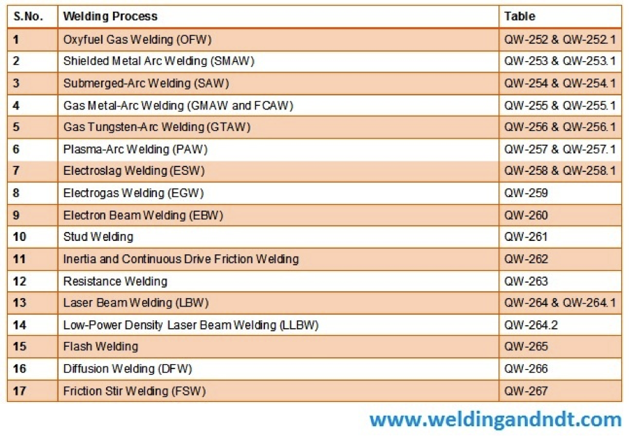
A welding procedure specification shall contain, as a minimum, the specific essential and nonessential variables that are applicable to the welding process. When the referencing code, standard, or specification requires toughness qualification of the welded joint, then applicable supplementary essential variables shall also be provided in the WPS.
These variables are listed in tables from QW-252 to QW-257. Please note that for each welding process, there is a separate table containing the list of all variables. For example, a list of variables (essential, nonessential and supplementary essential) for Shielded Metal Arc Welding (SMAW) is given in table QW-253.
Please see the below table (Table-1) for a complete list of welding processes and their corresponding tables for variables (as per ASME Section IX).
Table-1
Steps to be followed for preparation of WPS:
First of all, we need to identify the welding process which is to be used for example whether it’s a SMAW or GMAW or GTAW or any other welding process or it’s a combination of two or more welding processes. Once the welding process is decided then we need to see the corresponding table (QW-252 to QW-257) for the complete list of variables. With the help of the table, we can list out all the necessary variables to be used in our WPS.
Once the minimum variables (essential, nonessential and supplementary variables, if any) are decided a preliminary WPS (or proposed WPS also known as pWPS) is prepared.
Based on the proposed WPS, a Test coupon (or coupons) is prepared, and the coupon is welded as per the values (or range) provided in the pWPS. All the real-time data (observed during the welding of the test coupon) are recorded.
After successful welding, the test coupon (or coupons) is subjected to a destructive test, and if the test coupon (or coupons) meets the minimum code requirement then the same pWPS is finalized and approved for further job. In case of any change, the same procedure is repeated till the test coupon doesn’t meet the minimum code requirement.
All the real-time data during welding of test coupon and destructive test report data is compiled into one document known as Procedure qualification record (PQR).
After the successful preparation of PQR, the final WPS is prepared and produced to the authorized welding inspector for final approval.
Sanjay Gaikwad, Consultant, Boilers & Heaters