Ash deposition problem in conventional coal-fired/fuel oil-fired/FBC boilers including mechanisms, latest technologies, and remedial measures.
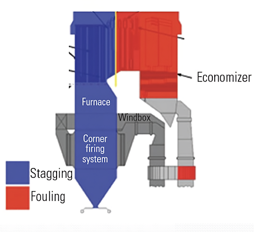
Ash Deposition – Fouling & Slagging
Introduction
Uneven ash deposition on fireside steam-generating surfaces of boilers may lead to alarming disturbances in circulation. The situation aggravates with higher steam generating parameters i.e. temperature and pressure.
For once-through supercritical pressure boilers, ash deposits on the water walls of the furnace bring about a large amount of temperature maldistribution. A large aggregate of slags detached from the furnace water wall can cause mechanical breakage of water wall tubes at the furnace bottom.
Fly ash clogs convective gas ducts with the effect that greater resistance is imparted to the motion of flue gas. This may result in a loss of steam-generating capacity as high as 50% of the rated value. Fly ash deposits on convective heat transfer surfaces build up additional thermal resistance and lead to a loss of boiler efficiency.
Process
The inorganic impurities in fuel like Sodium, Sulphur, and Vanadium are responsible for the ash deposition problem in boilers. Fuels used for steam generation contain a large variety of impurities in the form of inorganic material apart from the organic material that provides heat energy. During combustion, these impurities change their chemical form by combining with other constituents in the combustion regime. The effect of such combined materials being formed will be different at different sections of the boiler starting from the furnace to the air pre-heaters.
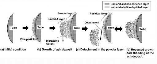
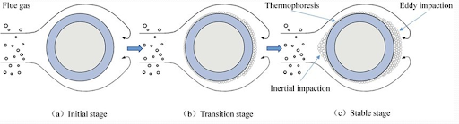
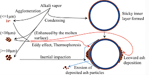
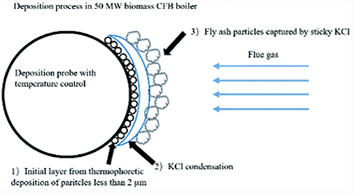
At the beginning of the deposition process, when the tube is clean, only vapors of KCl, K2SO4, NaCl, Na2SO4, and fine particles of Al2O3 & SiO2 will accumulate on the surface in a sticky condition. The deposit surface temperature goes up when the thickness of the deposit increases. Consequently, a molten film on the outer part of the deposit can flow down the side and form drops at the bottom of the deposit. Finally, these drops detach the tube when the surface tension is no longer capable of supporting the weight of the drops.
Classification of Ash Slags
When pulverized solid fuels are burnt, a part of the mineral impurities in the fuel, are melted. Depending on their melting point, viscosity, and thermal conductivity the ash particles adhere to the external surface of tubes leading to slag formation.
Ash slags can be classified as:
- LOW FUSIBLE ASH
- Contains compounds like NaCl, Na2SO4, CaCl2, MgCl2, Al2(SO4)3
- Melting Point 700-900˚C
- MEDIUM FUSIBLE ASH
- Contains compounds like Na2SIO3, K2SO4, FeS
- Melting Point 900-1100˚C
- HIGH FUSIBLE ASH
- Contains compounds like CaO, MgO, Al2O3, Fe2O3
- Melting Point 1600-1800˚C
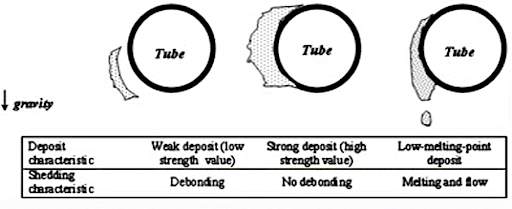
There is another convenient way to classify ash deposits. Depending on the bonding characteristics of ash particles and the mechanical strength of the deposited layer, ash deposits are classified into:
- Loose Deposit:
Loose deposits are deposits that form without chemical reactions and contain no sticky component in the matrix.
- Bonded Deposit
A bonded deposit is a denser layer of slag firmly bonded to heat transfer surfaces. At higher flue gas temperatures, most of the ash particles suspended in the flue gas remain in the plastic stage and form a sticky mass on the outer surface of the water wall and superheater tubes.
It quickly grows in thickness by arresting fly ash particles from flue gas and subsequently, such physico-chemical processes may occur to strengthen the bond.
Bonded deposits are mainly encountered in solid fuel-fired boilers. They are also known to occur in oil-fired boilers if fuel oil contains mineral components such as sodium, vanadium, calcium, and magnesium.
Factors Responsible for the Formation of Ash Deposit
Principle factors responsible for the formation of bonded ash deposits are:
- Mineral matter present in the fuel
- Behavioural pattern of mineral constituents of fuel
- Furnace temperature
- Heating rate
- Time of exposure of mineral matter of fuel to high temperature
- Flue gas composition
- Temperature of flue gas, fly ash, and heating surfaces in those zones where the formation of ash deposits is more likely
- Physico-chemical processes taking place inside the deposited mass of ash
Fusibility of Ash
The fusibility of ash is determined by the amount of different metal oxides and silica present in ash. These metal oxides (CaO, MgO, Fe2O3) form eutectics with silica (SiO2). Usually, ash produced by most solid fuels contains metal oxides in the range of 5 to 40 %. The higher percentage of metal oxides lowers the melting point of eutectic giving rise to low melting ash. Al2O3+ SiO2 content higher than 80% tends to increase the melting point of ash, which therefore becomes high melting. The mechanical strength of the primary ash deposit affects the slagging of the heat exchange surface of the boiler.
Strength of Deposit
The mechanical strength of ash particles is determined by their compressive strength. Based on different compressive strengths, the ash deposits can be divided into:
- LOOSE DEPOSIT
Compressive Strength < 1 MN/M2
- DENSE DEPOSIT:
Compressive Strength 1 to 3 MN/M2
- STRONG DEPOSIT
Compressive Strength 3-7 MN/M2
- VERY STRONG DEPOSIT
Compressive strength >7 MN/M2
I MN = 101971.62 Kgf
I MN/SQ.M = 10 Kgf/cm2
Mechanisms of Ash Deposition
Generally, the following five main mechanisms contribute to ash deposition.
- Condensation
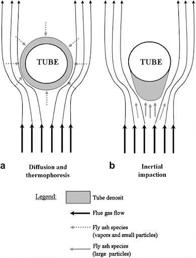
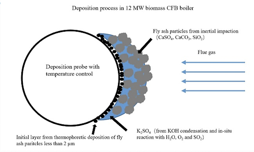
- Thermophoresis
- Brownian diffusion
- Inertial impaction
- Chemical reaction
Condensation
Condensation is the mechanism by which vapors are collected on a surface cooler than local gas. It happens either heterogeneously on the tube surface or homogeneously on the surface.
The inner layer is formed due to the condensation of low melting ash from flue gases on the tube surface as a thick sticky film that arrests the high melting fine ash particles falling on it.
Saturated with fine ash particles, the molten slag on the tube surface solidifies to form a primary dense layer of slag firmly bonded on the tube surface. The temperature of the outer surface of the primary layer then gradually increases and inhibits further condensation of low-melting ash from flue gas.
Therefore, further deposits of high melting ash particles on the rough outer surface of the primary layer become loosely held and they form a secondary layer.
Thermophoresis
Thermophoresis is a force generated by the temperature gradient between the hot gas and the cold wall affecting the particulate movement towards the cold wall. This phenomenon is observed in mixtures of mobile particles where the different particle types exhibit different responses to the force of a temperature gradient. It is caused by the temperature gradient so the movement of fluid molecules in the hot zone and high energy levels in this region displaces the nanoparticles towards the cold region.
This force transmits gas-borne particles of size less than 10 micrometers to 30 micrometers towards the lower temperature regions, such as a radiant section of the boiler. Thermophoresis is also referred to as Thermo migration, Thermo diffusion, or Soret effect. Soret number is the ratio of temperature difference to the concentration. The rate of change of temperature with displacement in a given direction as with an increase in height gives a database for studying the thermophoresis effect.
Brownian Diffusion
Brownian diffusion is the characteristic random wiggling motion of small particles resulting from constant bombardment by surrounding gas molecules. This pattern of motion typically consists of random fluctuations in a particle position inside a fluid sub-domain, followed by a relocation to another sub-domain.
It is the dominant particle deposition mechanism for small particles over short distances. Brownian coefficient depends on Boltzmann’s constant (1.38×10⁻²³J/K). The larger the value of this coefficient the more rapid the mass transfer from regions of high to low temperatures.
Impaction
Inertial impaction is the mode of transport for large particles to heat exchange surfaces. The particles subjected to inertial impaction are usually greater than 5-10 micrometers in size.
To impact a force, the large particles must have enough inertial momentum to overcome the drag force of the gas flow on the particles. Smaller particles will tend to succumb to the drag effect and follow the streamlines.
Eddy impaction is another important transport mechanism. It acts on particles in the range of 1-10 micrometers and those susceptible to diffusion and thermophoresis. These particles do not have enough inertia to impact on front side of the tube. However, they may accumulate on the back side of the tube.
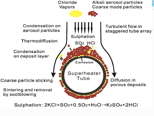
Chemical Reaction
The flue gases are cooled in the vicinity of the tube’s boundary layer, thus the vapors KCl, K2SO4, NaCl & Na2SO4 diffuse towards the cooling surfaces and condense on it, causing a sticky layer on the surface. The presence of this sticky layer is then essential for solid particles to be captured on the tube surface.
The deposit’s outer surface temperature increases as its thickness so at a certain temperature, higher than the saturation temperature of condensable species the condensation process stops. The mechanism by which ash can be accumulated in a deposit is completely by chemical reactions. These reactions include the heterogeneous reactions of gases with species in the deposit.
The most significant chemical reactions with respect to deposit formation are:
- Sulphidation
- Alkali Absorption
- Oxidation
Formation of Compounds
Compounds that have been recognized as having the potential to form in deposits and cause fire-side corrosion of tube surfaces include.
- PYRO-SULPHATE Na2S2O7, K2S2O7
- ALKALI-IRON TRI-SULPHATE Na2Fe (SO4)3, K2Fe (SO4)3
- MIXED SULPHATES Na2SO4, K2SO4
In considering the possibilities for such compounds to form in deposits, it is essential to assess the melting point of the compounds and the conditions necessary for their formation.
- Flue gas temperature: 1000-1650
Furnace water wall
Sodium/Potassium pyrosulphates
- Flue gas temperature: 650-1000
Superheater tubes
Alkali Iron Trisulphates
- Flue gas temp150-370
Economizer tubes
Mixed Sulphate/phosphorous pentoxide-rich deposits
Sulfidation
Sulfidation proceeds via the following stages
- Na & K in the coal become oxides.
- 4Na + O2 = 2Na2O
- 4K + O2 = 2K2O
- Sulphur in the coal becomes SO2
- S + O2 = SO2
- SO2 becomes SO3
- 2SO2 + O2 = 2SO3
- Na2O + 2SO3 = Na2S2O7
- K2O + 2SO3 = K2S2O7
- Carbon deposits within ash either by Unburned coal
- 2CO = CO2 +C
- Sulfidation by either
- SO3 + 3C + Fe = FeS +3CO
- SO3 + 9C + Fe2O3 = FeS + 9CO
Conditions For Sulfidation
The temperature of the tube surface must be high enough so that mixtures of Na2S2O7 & K2S2O7 exit in the molten state. The exact temperature depends on relative amounts of Na & K in coal. Carbon from unburned coal is unlikely to be sufficiently active to set up a reducing environment at these tube metal deposit interfaces. The decomposition of CO would give a finer, more uniform, and perhaps more active form of carbon within the deposit matrix.
Hydrogen Sulphide/Vanadium
Hydrogen sulphide is the main component in furnace gases, responsible for ash deposition. It proceeds via the following steps
- H2S + Fe = Fes + H2
- FeS + 2O2 = FeSO4
The ferrous sulphate (FeSO4) layer produced on the tube wall surface flakes off due to erosion exposing fresh tube metal to further ash deposition. Vanadium corrosion refers to the attack of superheater tubes by the vapors of vanadium pentoxide formed in flue gases.
If fuel contains sodium, the flue gases will contain, among other, sodium vanadate (Na2OV2O5), a low fusing compound (M.P. 600⁰C) forming a thin film of liquid on a superheater tube surface at 610-620⁰C. This film attacks carbon, low alloyed, and austenitic steels. The corrosivity of V2O5 increases in combination with sodium pyrosulfate Na2S2O7.
Sulphation
It is a kind of sintering that may occur in the furnace if there is an unfavorable mineral composition in the fuel. If the CaO content in the ash is more than 40% and if SO2 is present in the flue gas, the process of sintering may start on a loosely deposited layer formed on heating surfaces. This results in the growth of dense/ strongly bonded slag deposits on tube surfaces of water walls, platens, and superheaters.
CaO+SO2 + 1/2 O2 = CaSO4
Ash Deposition in Fuel Oil-Fired Boiler
- Fuel oils burnt in boilers are characterized by low ash content (0.07 – 0.15%), whereas some of them are rich in Sulphur (3 – 3.5%)
- Ash of fuel oil contains an assortment of mineral fractions-mainly the compounds of Ca, Mg, Na, Si, V & Fe
- These specific mineral impurities together with a high content of Sulphur led to ash deposition
- When fuel oil is burned, the combustion products contain all sorts of vanadium oxides i.e., VO, V2O3, V2O4, and V2O5
- Higher valent oxides have lower melting points and hence are more harmful from the point of fouling
- Fouling of waterwall tubes in the form of sticky deposits begins at a temperature above 815K. This sticky film of sodium vanadium (5Na2O.V2O4.11V2O5) attracts fly ash particles
- With the increase of surface temperature, the layer becomes more plastic and capable of retaining a higher load of fusible fractions of fly ash
- As a result, the overall process leads to the formation of a strong bonded deposit
- Na/V ratio plays a very important role in determining the characteristics of deposited ash in fuel oil-fired burners. With the increase of this ratio in ash, its sticky property increases. It is found to be maximum when this ratio is in the range of 3.7 – 9.5
Ash Deposition in FBC Boilers
- In fluidized bed combustion solid fuels reduced to 1-6 mm size can be successfully burnt in a fluidized state over a grate at the bottom of which combustion air is blown off
- The velocity of air is so controlled that the fuel particles are lifted off and reciprocated in the vertical flame
- The finer and partially burned coal particles are carried to the upper layer of the fluidized bed, whereupon their flow velocity decreases, and they undergo complete combustion
- The thickness of such bed varies from 0.5 M to 1 M & temp. around 800-1000˚C
- The specific characteristic of a fluidized bed is that it expands in volume by 1.5 – 2 times during operation
- Boiler tubes are placed in the form of inline or staggered tube bundles arranged in and above the bulk of the fluidized bed
- Fluidized bed boilers can be categorized into 2 main groups:
- Atmospheric fluidized bed boiler
- Pressurized fluidized bed boiler
- A.F.B. Boilers are of 2 types:
- Atmospheric Bubbling Bed Boiler
- Atmospheric Circulating Bed Boiler
- AFB Boilers can be subdivided into
- Bubbling bed with in-bed tube
- Bubbling bed without in-bed tube
- Circulating fluidized bed with external heat exchanger
- Circulating fluidized bed without external heat exchanger
- Bubbling bed boilers have in-bed evaporator tubes and superheater tubes
- The fluidizing velocity of air is the fundamental distinguishing feature of the fluidized bed combustion process
- Bubbling beds have lower fluidization velocities i.e., 1.2M/S to 3.6 M/S
- CFB has higher velocities i.e., 3.6M/S to 9M/S
Degree of Fouling
- The degree of fouling depends on:
- Time of exposure of tube surface
- Size composition of ash particle
- Flue gas flow velocity
- Mode of layout
- As the exposure time increases, the fouling coefficient also increases
- Finer particles cause more intensive fouling than coarse particles
- The lower the flue gas velocity, the thicker is deposition
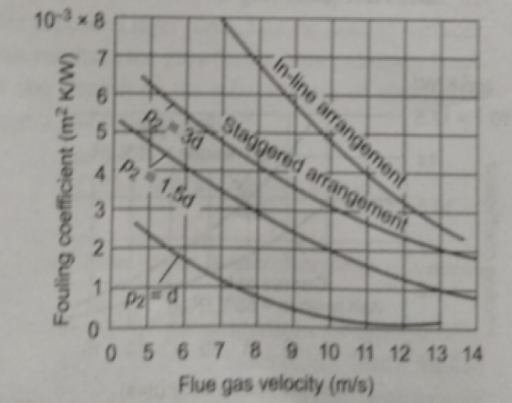
- The mode of layout is staggered, and the thickness of the slag deposit is more. If it is in line, then the thickness of the deposit is less
Effect of Gas Flow Velocity on Degree of Fouling
- The degree of fouling is determined by the thickness of loose deposits comprising chiefly of medium fractions (10-30 micrometers)
- Ash particles in this range continuously settle on the tube surface while ash particles in the coarse range (> 30 micrometers) continuously destroy the layer on collision
- Ultimately the final thickness of the deposited loose layer is governed by the dynamic equilibrium between these two processes
- As the flow velocity of flue gas increases, the kinetic energy of ash particles increases & with the rise destructive effect of coarse particles in proportion to the third power of velocity
- Therefore, the net result is that the thickness of loose deposits on the tube surface decreases
Effect of Arrangement of Tubes in Furnace on Degree of Fouling
- The tube fouling depends not only on the type of tube arrangement (staggered/in-line) but also on the longitudinal pitch of bunches
- Under the conditions of identical gas velocity and tube diameter, the fouling coefficient for in-line tubes is about 2 to 3.5 times that for staggered tubes
- It is not advisable to operate the pulverized coal-fired water-tube boiler at gas velocity as low as 3-4 m/s as the degree of fouling of fireside heating multiplies with the fall of flue gas velocity and it increases significantly. Nominal gas velocity at rated load should be 5-6 m/s
Effect on Heat Transfer Coefficient
The overall heat transfer coefficient is reduced by the loose deposit of ash particles.
Thermal Conductivity = QL/AΔT
Where,
Q = Amount of heat transferred through material in Joules/second
L = Distance between two planes
A =Area of surface in m2
Thermal Conductivity = W.M/M2.Kelvin
= W/M Kelvin
Fouling Coefficient = Thickness of slag/conductivity of slag
= m.mk/w
= m2k/ w
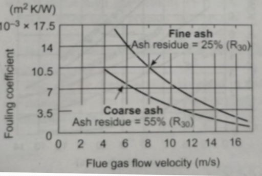
Flue Gas Velocity vs Fouling Coefficient
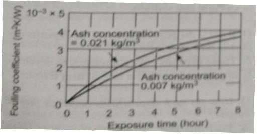
Fouling Coefficient vs Exposure Time
Effect of Coal on Deposit
Sudden changes in heat flux as those caused by using coals of varying CV result in higher scale deposition and consequently higher metal temperature and higher oxide growth on the steam side leading to exfoliation. For the same flow of coal, the coals with higher GCV will give higher heat flux compared to coals with lower GCV, so whenever imported coal is used the boiler tubes are subjected to higher heat flux compared to lower heat flux from Indian coals.
The reverse occurs during the changeover from imported to Indian coals. In either case, boiler tubes are subjected to changes in heat flux causing additional stresses on internal oxides and external scales which spill off paving the way for further oxidation/fouling.
Imported coals are softer coals and are rich in alkali and alkaline earth metals which tend to soften during the combustion process. These softened materials form a thin film over the tube surface where subsequently they react with Sulphur compounds to form pyrosulphates. The slagging and fouling tendency of such coals is higher. On the other hand, Indian coals have high silica, and alumina, which are abrasive and are responsible for higher erosion.
In either case, some ash is deposited over the boiler tube surface (external surface) which results in high heat being experienced by the tube metal. Internal steam side metal temperature is affected which changes the steam oxidation of boiler tubes (S.H. & R.H. tubes are more prone to this phenomenon).
During start-up and shut-down processes the oxide film which may have multiple layers, is subjected to differential coefficients of thermal expansion resulting in spalling/exfoliation of the oxide layer and exposing fresh tube surface to further oxidation.
Technologies Available for Prevention of Deposition Problems in Boiler
- There are some ash behaviour prediction tools like Ash Pro (SM) used to assess the slagging and fouling situations in coal-fired boilers, integrating boiler computational fluid dynamic (CFD) simulations with ash behavior models including ash formation, deposition, deposit growth, and strength development
- These prediction results are very important to assess the overall performance of power plants including fuel quality, ash properties, fouling, slagging, etc.
- The characterization of ash is extremely important to predict the mineral transformation in coal particles during combustion, which controls the characteristics of resulting ash particles
- Computer Controlled Scanning Electron Microscopy (CCSEM) and Scanning Electron Microscopy Point Count (SEMPC) methods are available today to fully characterize ash with respect to the ash deposition process
- As a result, a direct comparison can be made between coal mineralogy and that observed in the ash sample
- This is of fundamental importance as it provides the database from which the relevant ash-deposition models can be constructed
- Thus, it is possible to establish the effect of coal preparation (grinding, pulverizing, and cleaning) and combustion conditions on the size and mineralogy of ash particles
Ash Deposit Characteristics
- Fine, light-colored, reflective, thin layered depositing at W.W. at all types of boilers and dense and molten slag deposit covering patches or entire W.W. area at p.c. fired boilers
- Sticky ash rimming around the burners (called eyebrows) or accumulating on W.W. near Burner
- Highly fused, very porous slag with bubbly appearance (termed vesicular) depositing at 2-3 m above Burner
- Sandstone-like feathered fouling deposits on the front edge of the tube of R.H
- Alternating light grey and brown or red deposits at primary S.H./R.H
- White to reddish brown depositing at L.T.S.H./ECO
- Very fine light brown or grey ash depositing at A.P.H
C.C.S.E.M. AND S.E.M.P.C.
- S.E.M.P.C. involves the systematic microprobe analysis of over 240 points within a suitably prepared sample
- C.C.S.E.M. analysis of ash samples establishes an estimate of the size distribution of major species
- S.E.M.P.C. data is used to establish the amount of liquid phase available in the sample
- Factors which control the probability of deposit initiation are:
- Size, shape & momentum of ash particle
- Temperature
- Amount of liquid phase on the surface of a particle
- Base/Acid ratio of liquid phase
- Viscosity & surface tension of liquid phase
- Structure & nature of metal surface
Method of Analysis
- The viscosity of various phases is computed by particle basis and data is presented in the form of population Histograms called viscosity distribution
- Viscosity is then calculated at a given temperature
- Usually, the gas temperature in the region of the surface of the target is taken for calculations
- By studying the data one can establish a scale or relative degree of sticking probability of the targeted surfaces
- Ash with a high population of low-viscosity liquid phases will tend to form a deposit on a metal surface than ash with a bulk of amorphous phases with high viscosities
- It is the proportion of the liquid phase and its viscosity in the ash particles that plays the primary role in ash buildup on the tubes
- Coals that form ashes with smaller-sized particles, and lower amounts of surface liquid phases have a low probability of sticking on the targeted surfaces as the initial layer
- From CCSEM and SEMPC analysis, we get the size distribution of the ash particles, the phase distribution, viscosity, and the chemical composition of the liquid phases on a particle-by-particle basis
- Use of this data can be made to gain some insight into the degree or relative degree of sintering the ash particles will undergo within the deposit and that will enable us to assess the degree to which the surface of the deposit will become the dominant factor in the rate of growth
- It is convenient to review the complex process with respect to measurable parameters
- We can use the data from CCSEM and SEMPC analysis to assess the extent to which a captive liquid phase will form and hence the rate of growth
Micro Beam Technology
- Microbeam Technologies Inc (MTI) provides advanced quantitative information on the impurities in fuels, ash behavior, and determining and predicting the effect of ash on power system performance using CCSEM
- MTI processes also identify problematic deposits, slagging, and fouling
- This predicted information is very useful in the reduction of abrasion & erosion, slag flow problems, convective pass fouling, ash resistivity, and deposit strength
Heat Flux Meters
- Heat flux meters can be used to study thermal absorption diagnostics in boilers as a part of the boiler-monitoring systems
- These sensors can be installed at power plants by a supplier of soot-blowing systems though it is difficult to quantify the energy saving obtained from the development and application of such a sensor
- Continuous fouling formation on heat transfer surfaces is a great problem in existing conventional coal-fired utility boilers
- A cost-effective way to minimize this difficulty is the continuous monitoring of fouling tendencies in the boiler as a tool of operation
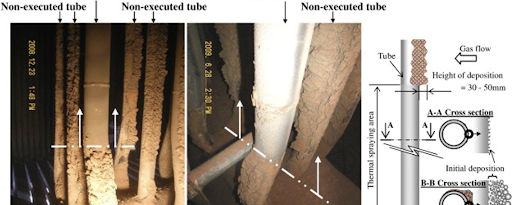
Targeted In Furnace Injection (TIFI) Technology
- Chemicals are injected into the flue gas system after mixing with water and air
- Magnesium hydroxide slurry diluted with water and then atomized with air is the most common application of TIFI technology
- This mixture is sprayed into the furnace at computer-determined ports that allow for complete coverage of problem areas
- These cause a chemical reaction with existing deposits and affect their physical crystal characteristics
- This chemical treatment program is successfully applied for the inhibition and reduction of slag formation in the superheater, reheater, and furnace wall sections
- This technology is used in western USA coal-fired utility boilers to control slagging. fouling and tube cracking
- This technology involves different forms of fluid dynamics modeling
Pulse Detonation Wave Technology
- This technology is based mainly on a supersonic combustion process
- A shock wave is propagated forward due to energy released in a reaction zone behind it, where an ignited fuel/oxidizer mixture burns and releases energy
- The significant characteristics of the pulse detonation technology are high temperature, high velocity and high-pressure waves producing direct impact, thermal stresses, high reflection and wave reverberations and exceptionally high shearing capacity to remove slag and fouling deposits
- P.D.E. (pulse detonation engines) are very effective for producing detonation waves (strong waves) for removing ash deposition without damaging the boiler
- P.D.E. is powered by an electric motor and injection valves feed the combustible fluid into the ignition section. Instruments mounted on different sections of the device are necessary to check the performance of the engine. These instruments include pressure transducers, thermocouples, and thin film gauges
- Researchers have found that softer slags are removed more easily with multiple waves. The Slag on the top of the tube generally breaks up into smaller pieces when exposed to waves, while the slag on the side of the tube and in the webbing shears off
Internal Cameras
- Internal cameras (3.9-micrometer band) can be used to monitor the fouling problem
- Special infrared cameras for this purpose are designed to scan the fouling by filtering the light from the boiler. This allows the camera to see through the flames to the walls by blocking the appropriate wavelengths
- These types of cameras are hand-held and thus must be used through viewpoints
- Internal cameras can be installed in areas that are prone to ash buildup or can be installed in adequate numbers to cover all relevant areas of the boiler
- If rotatable cameras are used, they will also be able to see multiple places of the boiler
Location/Phenomenon/Counter Measures
A. S.H. & R.H.
| External | Internal | Phenomenon | Counter Measures |
| High Temp. Corrosion | Steam Oxidation | Corrosion by low molten coal Alkali Iron Sulphate Oxidation caused by steam | Thermal spray High chromium material Composite tube Additives |
B. Furnace Water Wall
Sulfidation corrosion
| Phenomenon | Counter Measures |
| Corrosion loss caused by hydrogen sulphide in Reducing atmosphere combustion gas and iron sulphide in deposit ash | Improvement in combustion efficiency Thermal Spray Clad Welding |
C. Burners
Oxidation, Sulfidation
| Phenomenon | Counter Measures |
| COxidation /Sulfidation at high temperatures (>1800°F) | Heat resistance material |
D. Economiser
Low Temperature Corrosion
| Phenomenon | Counter Measures |
| Sulfuric Acid Dew Point Corrosion | High Cold End Metal Temperature Corrosion Resistance Materialrial |
E. CFB BOILERS
- It has been possible to battle out ash deposition problem in the most aggressive environment of CFB with the advent of new spray processes, such as Electric – Arc Wire and HVOF (High-Velocity Oxygen Fuel) and improved coating materials like
- Iron – based alloy containing 30 % Cr
- Low carbon steel similar to the material in the existing weld overlay
- The goal of weld overlay is ultimately to improve the properties of the base metal and cladding is a process where different tougher material is applied than the base metal
- Many CFBs have an external heat exchanger which helps to compensate the changes in load conditions and fuel properties for controlling heat absorption rate in the furnace
Author
Pramod P Kate
Vyankatesha Engineers and Consultants, Nagpur
Boiler Technical Consultant