Introduction
Chemical industries are very important for the national economy as they make a significant contribution to the industrial production of the country. Items for personal hygiene, fertilisers for agriculture, high-speed diesel, petrol for land-based and ATF for air transport, furnace oil, propane for industrial use; paper, plastics, synthetic fibres and LPG for domestic use; explosives for defence and mining, pharmaceuticals for healthcare, etc. are provided by the chemical industries.
It is necessary to minimise the cost of production in order to make the products competitive in domestic as well as international markets. This can be done by controlling the costs of raw materials, plant equipment and machinery, manpower, and maintenance expenses and minimising energy consumption.
Modern management ensures that the raw materials meet the specifications (laid down by production engineers) to get proper product quality and are procured at a minimum landed cost; the equipment and machinery have the capacity to manufacture the products in a safe, efficient manner; and by employing suitably qualified and experienced manpower for operating and maintaining the process plants. Efforts are made towards the recovery of heat by installing waste heat recovery equipment (boiler, economiser, air pre-heater etc.), which can contribute to meeting the heating energy needs of the plant.
Advantages of heat recovery boilers
These can reduce environmental pollution, reduce the size (and area) required for the equipment, reduce the power consumption of main air blowers used (for gas flow) by reducing the pressure drops on the gas side; and reduce the cost of energy by co-generation when the recovered heat is used for both power generation as well as process heating.
Examples of sources of waste heat
Following are some of the industries where waste heat can be available in high-temperature process gases, such as:
- exit gases from cement kilns
- exit gases from Copper ore smelting
- Sulphuric acid and Oleum plants (burning of sulphur and reaction heat from converter)
- Exit gases from Incinerators of industrial wastes
Heat can also be recovered from hot sulphuric acid circulating in the absorber circuit of sulphuric acid plants. The readers are requested to refer to Chapter 9 on Heat Exchangers in Process Equipment Procurement in the Chemical and Related Industries (PHE Based Heat Recovery System, Pages 105-107) published by Springer International Publishing, Switzerland, by this author for further information.
Operation of the chemical industries
Generally, these are run continuously around the clock (24 x 7), while some plants are run in a batch-wise manner. The priority of the process plants is to run them safely, efficiently and in a pollution-free manner in order to manufacture the products at the lowest cost. Co-generation of power and steam is next on the priority list.
Utilities required by chemical industries
Electrical power (AC and DC), steam (at different pressures), compressed air, process (treated) water, cooling and chilled water; low temperature brines
Process units that need electrical and heat energy:
- Pumps, blowers, mixers, agitators, conveyors (electrical energy)
- Some typical units are melters for sulphur; evaporators for dilute alum solution, and process reactors with steam in the heating jackets. These units may need steam continuously, intermittently, or at variable rates throughout the day
- Condensers, chillers, absorbers (Cooling water from cooling towers / chilled water or low temperature brines which need refrigeration)
- Steam shall be required for plants having installed Co-generation facilities
General arrangements for meeting the needs at present (before installing WHR equipment)
- By drawing power from the external grid
- Steam generation by own coal-fired boiler
- Cooling hot process gases for downstream processing by exposure to atmospheric air ( an old practice which is not followed now)
- Cold water from cooling towers
- Chilled water/low-temperature brines provided by refrigeration units
Management Options:
- Obtain (purchase) electrical power from the external grid
- Obtain (purchase) steam from neighbouring industries where excess capacity may be available or continue to generate steam in-house only for process heating
- Install facilities for Cogeneration: Generate power by steam turbines and use steam from turbine exhaust for process heating. However, it is necessary to correctly estimate the power and steam requirements for the present (and for the future expansion) of plant capacity before investing in these facilities.
Techno-economic considerations
An evaluation of the above options shall be carried out by a detailed study of the present process, the running time of various process units, their requirements for power and steam, the cost of purchased energy; operating and maintenance costs of energy generated in-house through energy recovery equipment and the adverse effect of the non-availability of power/steam even for a short time on plant safety, production loss, product quality.
Hence, the steam drum should have the capacity to accumulate steam to take care of such a situation. Alternatively, a spare quick-start boiler of smaller capacity and DG sets shall be kept ready.
Potential for heat recovery
This shall be calculated by considering the expected flow rates of hot gases at different production rates, their composition, their corrosive nature, the additional equipment required to ensure their smooth functioning, and the temperature at the inlet and exit of the WHRB at various plant production rates.
It should be noted that the cost of fuel can be considered negligible when heat is to be recovered only from hot gases and no supplementary fuel is required.
Comparison of WHRB with Conventional Boilers
- The operating pressure of WHRB (15-42 kgs/cm2 is generally lower as compared to boilers in Thermal Power Plants which operate at 90-120 kgs/cm2 or even higher
- Operating time: Power boilers run continuously for power generation while WHRB is operated continuously OR intermittently as required for running the process plant. They can be occasionally bypassed also as per the temperature of gases required in downstream process units.
- Fuel: Power boilers/conventional boilers are operated on coal, furnace oil, LDO and natural gas where the cost of fuel and facilities for their transport and feeding to the combustion furnaces must also be considered. These fuels have higher calorific value and are used for continuous steam generation.
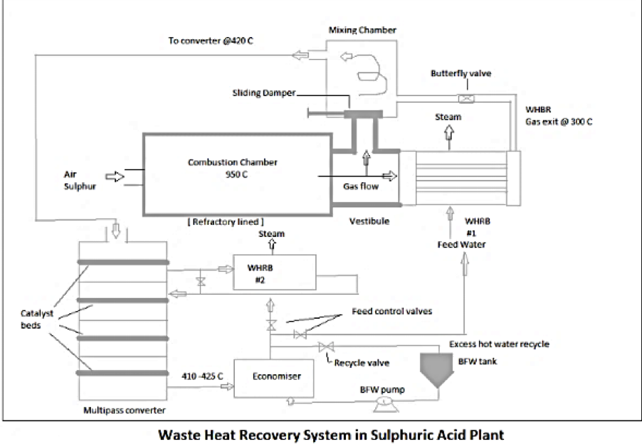
- WHRB in chemical plants generally do not use fuels like coal, furnace oil, natural gas, etc when they are installed to only reduce the temperature of hot gases for further processing in downstream units (for example temperature of exit gases from sulphur burning furnace is reduced from 950-980 deg C to 415–425 deg C before admitting to the converter for converting the SO2 to SO3 ). In such cases, the cost of fuel can be considered as zero.
- WHRB in Waste Incineration Plants: These are operated on low CV fuels like Distillery Spent Wash, Municipal Solid Waste (where the cost of fuel is not zero due to pre-treatment required) along with some supplementary fuels for sustaining the combustion of low CV fuels. The steam generated by such WHRB is used for power generation and concentration of the dilute Distillery Spent Wash, drying wet MSW.
However, the cost of fuel can be offset by the advantage of achieving environmental pollution control.
- Fuel feeders: Conventional boilers use silos and screw feeders for pulverised solid fuels; centrifugal pumps for fuel oils, and pneumatic feeders for small steam generating; whereas WHRB in chemical plants needs controlled gas flow at the inlet.
- Installation: Power boilers and economisers are installed independently in the premises and provision is accordingly made for the supply of fuel, treated water, combustion air and finally release of flue gases from the chimney. In the case of WHRB and economisers, it is sufficient to connect ducts for the incoming hot gases and outgoing cooled gases and for bypassing the WHRB when required. (Please see below)
- Operation of the Boiler: The power boiler is on stream always in order to maximise the generation of steam. However hot gases from a WHRB can be bypassed (to maintain temperature in downstream process units as per production requirements).
- Steam Generation Capacity: Power boilers are generally designed to meet the requirements of turbines for generating electrical power. Steam generation is their first priority. Since WHRB is designed to reduce the temperatures of hot process gases at flow rates corresponding to the plant production at rated capacity (and for future expansion of the production capacity of the plant), their priority is to maintain proper temperatures in the downstream units. Higher steam generation is desirable, but it is their next priority.
- WHRB is also provided with some excess heat transfer area (if there are chances of deposits of dust particles or the presence of corrosive constituents in the gases). The excess area can cause more cooling than necessary of the hot process gases. Hence, it may become necessary to bypass the WHRB during operation in the initial few days. After a few weeks, the flow of gases bypassing the WHRB can be reduced (as the deposits build up on the heat transfer areas) and more hot gases can be passed through the unit. This is generally done at Sulphuric acid plants.
- During this bypassing the main WHRB generates less steam and is not able to consume all the hot water (being generated by the economizer and then pumped into it). It is therefore to be recycled back into the BFW tank. However, the recovered heat gets wasted as flash steam from the BFW tank.
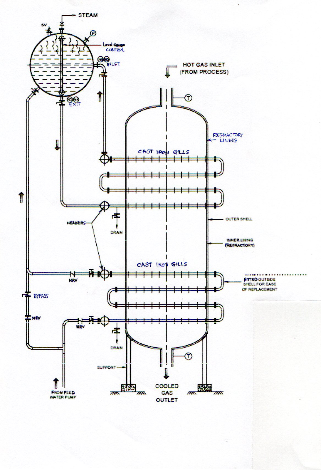
Modified economiser (Please refer to the figure below)
- A modified type of economiser (having a separate flash drum at the top and operating at lower steam pressure) is provided to address this problem. Water is heated by convection currents between the flash drum and the set of coils in the economisers. The hot water gets flashed in the drum and generates steam. The heat is thus recovered as latent heat from evaporation instead of sensible heat by the water pumped through the coils (as in the case of conventional economisers). Water is added directly to the flash drum by an automatic level controller to make up the quantity evaporated as steam. Hence, the feed water pump does not run continuously and operates only when the water level in the flash drum goes down to the set point.
- The arrangement thus saves power consumption by the smaller feed water pump provided and also prevents waste of recovered heat
- The WHRB continues to be fed by the existing BFW pump through the level controller. Since it now gets water at a lower temperature the flow rate and temperature of the gases from the combustion furnace can be increased if required for increasing the production rate of the plant.
Reference: Chapter 11 on Heat Recovery Equipment in Process Equipment Procurement in the Chemical and Related Industries (Steaming Economisers Pages 137-138) published by Springer International Publishing, Switzerland; by this author for further information.
.
Modified Economiser with Flash Drum
Design Considerations for WHRB
To check the suitability of the plant from a technical and commercial point of view by considering the operating pressures (high/medium/low); and the economic viability.
Type of Boilers
Smoke tube type, in which the hot gases flow through the tubes and water is on the shell side.
The shell and the tubes are both under pressure and hence they can cost more for the same working pressure.
Application: Sulphuric acid, Waste incineration plants
Water tube type, in which the hot gases flow through the shell and water is on the tube side. The shell is not under any pressure on the gas side (it is not subjected to steam pressure). Only the tubes operate under high pressure. Water tube boilers can quickly generate steam due to the smaller volume of water in the tubes and may cost less for a given working pressure.
Application: Power generation, Cogeneration (and sometimes for process heating)
Used in Thermal Power stations; the Sugar industry; Carbon Black manufacture
Heat Recovery Steam Generators are also used at the exit of power-generating gas turbines.
Duty conditions: To cool the hot process gases (from process units operating at higher temperatures) to the required temperature at the point of admission of downstream process units for further processing. Both the inlet and exit temperatures for the boilers should be specified and communicated to the boiler manufacturer.
It is necessary to consider the flow rates of hot process gases as normal when the plant is run at rated capacity; as maximum flow rate (corresponding to the future expansion of plant capacity) and as minimum flow rate (when the plant may have to be run at a lesser than rated plant capacity). It is also necessary to consider the normal, maximum and minimum temperatures of the gases likely at the inlet to the WHRB when the plant is run as above.
The specific heats of the gases in the operating range should be taken into account for calculating the cooling load and hence the heat transfer areas required. Adequate margin shall be provided due to fouling by dust particles and the deposit of scales by corrosion, if any.
Composition and properties of the hot gases It is necessary to correctly know the chemical concentration (as mole%) of the various constituents in the incoming hot gases, especially in the presence of gases like SO2 and SO3, which form corrosive condensates in the presence of moisture. It is important to check the dew point of the gases because there is a chance of deposition of this acidic condensate on the heat transfer surfaces of the boiler at lower temperatures. The concentration of erosive dust particles should also be considered.
It is imperative to properly treat the feed water and ensure that it meets the specifications laid down by the manufacturer. In a chemical plant, steam is often used for heating process vessels (handling acidic materials) and there are chances of the recovered condensate becoming acidic due to even a minor leak of the heating coils/jacket. It is advisable to provide online conductivity meters for the feed water and maintain alkaline pH by adding alkali if necessary. The water samples shall be regularly analysed in a chemical laboratory.
An audio-visual alarm may be installed in the feed water line if the water becomes acidic due to any reason.
Pressure drop permissible on the gas side
The power consumption by the main blower depends on the pressure drop in the system and hence it is necessary to check whether it can be reduced by modifications in the operating conditions; changes in equipment design; piping size and layout etc. The cross-sectional area provided by the boiler tubes (in a fire tube boiler)/boiler shell (in a water tube boiler) shall be designed accordingly and confirmed by the manufacturer.
The excessive cross-sectional area can result in lower gas velocities and reduce the heat transfer coefficient in a fire tube boiler. Hence, in certain designs, loose ceramic screws all along the length are provided inside the tubes to give a rotary motion to the gases. These also help to reduce deposits of scale on the surfaces of the tubes.
The layout of the process plant: The process plant is generally erected on well-level land. However, tests shall be carried out to check the load-bearing capacity of the land since the WHRB are quite heavy equipment and can subject the area to concentrated loads.
WHRB are to be installed in the process plant between the source of the higher temperature process gas stream and downstream process units operating at lower temperatures. The location is thus dependent on the space available between these process units and the layout of the production facilities. It is generally predetermined as per the design of the process plant for the present (and future expansion) capacity.
Hence, sufficient space should be kept available in the process section to accommodate the WHRB, hot gas vestibule and bypass tower, economisers; work platforms, condensate recovery piping and control instrumentation.
Clear space shall also be available around the WHRB for installing boiler feed water tanks and water pumps; for the incoming and outgoing gas ducts; their supporting structures and for cleaning the shell and tubes during annual shutdown (generally carried out by circulation of inhibited chemical solutions by the temporary provision of a chemical tank and circulation pumps and connected piping.) The spent acidic solution after cleaning shall be properly treated in the effluent treatment plant and reused elsewhere on the premises.
Design and construction of the civil foundation
Support pad plates for the boiler shall be designed for maximum operating weight after taking into consideration the maximum weight of the boiler and vestibule; the weight of the boiler with mountings plus inside water, connected gas ducts, work platform, ladder, connected steam lines etc. It is advisable to design and construct civil foundations with a sufficient safety factor and consideration of earthquakes of 7.0 magnitudes on the Richter scale.
Freedom for thermal expansion of the connected vestibule and combustion furnace should be available through the provision of rolling supports at the free end. The ducts for incoming hot gases/ducts for exit gases should have sliding supports.
The positions of pockets for foundation bolts (as shown on the civil drawings) should match with pad plates and shall be as per advice from the boiler manufacturer. The foundation bolts shall be supplied by the boiler manufacturers or the procured bolts shall be approved by them.
The design, construction and curing of the civil foundation as well as the grouting of foundation bolts shall be approved by civil engineers before placing the load on the boiler.
Electrical earth connections and a lightning arrester should also be provided for the protection of the system.
Blow-down vessel and connecting piping shall be clamped and grouted securely if the boiler is fed with soft water (since it will need regular blow-downs to control the concentration of dissolved solids in the boiler water However, the frequency of blow-down is very low when demineralised water is fed into the boiler and it also saves energy losses through the blow-down of hot water).
In certain cases, WHRB is provided to recover heat from hot process gases that are exiting the plant where sufficient space is more readily available.
Orientation of the WHRB: Level gauges, Non-Return Valves, pressure gauge on the boiler; both safety valves, etc should be easily visible from the control room of the process plant.
The fabrication drawings, the material of construction MOC to be used for the shell and tubes, nozzles, etc. (i.e. all parts which be subjected to pressure), details of welded construction, provision of safety valves and trip devices will need approval by statutory authorities.
Manpower: Licensed Boiler attendants provided and their Span of Control (when more than one boiler is manned by a single person) shall also be as per advice and approval by Statutory Authorities
Annual inspection: The WHRB is normally inspected thoroughly by the Statutory boiler inspector and hence the programme of annual overhauling of the process plant should coincide with these inspection dates ( since it is generally not possible to run the plant without the WHRB) The plant shall be restarted only after getting written permission from the boiler inspector to resume operations.
In the event of derating the boiler- even after repairs-(as instructed by the boiler inspector), the process plant may have to be run at a reduced rate of production.
Effect of tube leak: Even a minor leak can cause severe process problems or environmental pollution (Oleum plants, nitric acid plants). In the case of power boilers, there will be only steam loss through flue gases, which contain water vapour even during normal operation.
Commissioning and Cogeneration
Boiler Feed Water Pumps: It is necessary that these pumps work satisfactorily when the process plant is commissioned and thereafter run at rated capacity (since it is not advisable to reduce the production rates once a steady plant run is established).
This can be done by confirming the discharge capacity of each BFW pump against the maximum working pressure of the economiser/boiler, which can be created by throttling the outlet valve and running the pump to feed water. This shall be done before the heating of the process plant units is started.
The discharge capacity (water feed rate) of the pumps is then measured by either collecting the exit water in a tank or by noting the fall in the level of the BFW tank.
The current drawn by the drive motor in each phase is also to be measured.
The flow rate should be at least 20% higher than the maximum rate of steam generation.
Boiling out: Initially, the boiler is filled with treated water and heated slowly while keeping the vent valve open. The steam generated is vented out. After about eight to twelve hours, the hot water is drained out and replaced by fresh water. About 3% alkali is added to the water to remove the oily matter (which is put on the tubes by the manufacturer). The oily content in the water is analysed and the procedure is repeated till there is no more residual oil or as per instructions from the boiler manufacturer.
Commissioning and integration with process plant
This takes a little longer than conventional stand-alone boilers because both the cooling of the hot gases and steam generation has to be done while maintaining operating conditions in downstream units as per the production rate of the process plant. It is also necessary to simultaneously meet the requirements of power and steam by various process units.
- The instrumentation for the boiler and feed water system ( pressure gauges, conductivity meter, level indicators and control valves; hot gases flow trip mechanism in case of very low water level etc) shall be confirmed to be in working order.
- The safety valves should be set to blow off as per instructions of the boiler inspector and the setting shall be locked in a tamper-proof manner.
- The boiler feed water tank shall be cleaned thoroughly and then filled with properly treated water as per specifications given by the manufacturer. Level indicator and water meter shall be provided. Condensate recovery piping shall be cleaned of all dust and scales.
- Thermal insulation and cladding on the boiler and economiser should be checked so that there is no chance of ingress of rainwater.
- Working of all valves ( NRV, feed check and isolation valves as well as Main Steam Stop Valve MSSV, blow-down valve ) on the water and steam side shall be confirmed to be working satisfactorily.
- Working of all valves in the gas inlet, outlet and bypass ducts shall also be checked.
- Initially, the boiler may have to be bypassed in order to bring up the temperature in the downstream units; while generating just sufficient steam for process use (melting of sulphur; heating of reactor jacket, keeping the liquid feed piping warm; maintaining a vacuum in process tank etc).
Gradually, the quantity of hot process gas streams that are bypassing the boiler can be reduced as the process plant operation gets stabilised and the rated production capacity is reached. Thereafter, the steam supply can be started to the turbine when the WHRB has reached normal working pressure.
Note:
- Steam generation by WHRB takes place as per the process plant operation rate (which is occasionally not very steady). The aim is to generate as much steam as possible (recover as much heat as possible) without disturbing temperatures in downstream units in the plant (for example converter, absorber in case of Sulphuric acid plants.).
- Since there can be occasional bypassing of WHRB it is advisable to have an additional independent source of steam in order to maintain a steady supply to the turbine. when captive power generation is also desired
- In case of excess generation of steam, it may be worthwhile to install job work facilities (making available space in the premises for the equipment and supply line for surplus steam for process work like concentration of dilute solutions, crystallisation, operation of tray drying units etc. The condensate can be taken back.
Power Generation
The electrical generator can be synchronous (if the expected generation is more than the captive demand) or induction type if the expected generation is likely to be less than the captive demand).
In the case of the synchronous generator, it is a stand-alone system and the process plant is independent of power supply from the external grid. The plant will keep on running even in case of an external grid power outage. However, in the case of an induction generator, it only helps to reduce the draw of power from the external grid.
A variant of the arrangement
The total electrical load as well as the power requirement of individual drives for equipment
(which generally run continuously) is to be studied in detail. Some of these can be provided with a dual drive arrangement (an electric motor and a steam turbine for driving the same equipment). This turbine is supplied with steam from the WHRB and the equipment is also driven by the motor.
The turbine shares the load on the motor and reduces the power consumption whenever the steam supply is available. Thus, it is possible to use the steam even when the boiler is partially bypassed (occasionally as per process conditions ) and the steam generation is not steady.
Disadvantage: It can be practically impossible to operate and maintain a number of such dual drives. However, it will be useful when a large portion of the electrical load is due to a single piece of equipment (for example the main air blower in a sulphuric acid plant)
In both of the above cases, the exhaust steam from the turbine can be used for process heating.
Typical reasons for malfunctioning/failure:
- The presence of corrosive gases (especially when moisture is also present ) reduces the life of shells, tubes and tube sheets.
- Deposits of dust cause inefficient heat transfer.
- Even minor leaks of boiler tubes can badly disturb operations in the process plant, create dangerous situations and cause heavy atmospheric pollution (Sulphuric acid and Oleum plants) due to the escape of acidic mist from absorbers.
- Initial provision of excess heat transfer area (hence bypassing becomes necessary later on) can increase the cost of the boiler.
- The calorific value of the hot medium is not constant if there is a variation in composition.
- The feed rate and temperature of hot gases are not always constant. They depend on the operation of the main plant
- A mismatch between the availability and requirement of heat can cause inefficient operations.
Remedial Measures
- Selection of process raw materials having minimum corrosive and erosive content.
- Use of dry air for combustion
- Screening/Filtration of raw materials
- Provision of protective refractory layers on the tube sheets (fire tube boiler)
- Provision of refractory ferrules on the inlet of boiler tubes (fire tube boiler)
- Installation of ceramic thermo-wells to protect the thermocouples in the combustion furnace that are used for temperature measurement
- Use of metering pumps instead of centrifugal pumps to prevent excess feeding of fuel / raw material into the combustion furnace
- Provision of alloy steel valve at gas exit duct of the boiler instead of refractory lined / alloy steel damper in the bypass hot gas duct. This arrangement prevents exposure of valve internals to hot corrosive gases since they are now in contact only with gases at lower temperatures from the boiler exit
- In certain smoke tube-type WHRB designs an internal bypass line is provided for the hot gases. The opening at the far end can be adjusted as per need. This eliminates the requirement for an external gas duct
- Feeding supplementary fuels like furnace oil, pulverised coal along with low calorific waste are fed to an Incineration plant in order to maintain a steady heat load.
Conclusion
It is hoped that the readers will be able to increase the energy efficiency of their plants by selecting the most suitable waste heat recovery boilers (and Economisers) and thus reduce the cost of production.
Author
K R Golwalkar
(Consulting Chemical Engineer)