Abstract
Working Pressure Formula (WPF) adopted by boiler codes determines the maximum pressure of fluid (steam/water) that can be permitted to be carried by cylindrical boiler components like boiler shells, drums, headers, and steam feedwater piping and fittings like valve chests. Thus, it plays a vital role in the sizing of boiler components. This article surveys the list of WPF along with their theoretical background and then compares the formulae adopted by Indian Boiler Regulations (IBR), ASME Boiler & Pressure Vessel Code (Section I), and ASME Power Piping Code B31.1.
Allowable stress (f) for a boiler component material limits the maximum possible stress (S) that is permitted to be induced in the boiler component. Codes compute allowable stress for a material specification based on the uniaxial tension test results such as Ultimate Tensile Strength (UTS) at room temperature and yield strength at design temperature (Et) for the ferritic boiler quality steels in the non-creep range service. For example, carbon steel pipe specification SA106 Gr B, with a minimum specified UTS of 4200 kg/cm2 and a minimum specified Et of 2400 kg/sq.cm at room temperature is assigned allowable stress of around 1200 kg/cm2. at room temperature by ASME Boiler & Pressure Vessel Code.
Maximum pressure (P) of fluid (steam/water) that can be permitted to be carried by cylindrical boiler components like boiler shells, drums, headers, and steam feedwater piping and fittings like valve chests, is limited by Codes based on the dimensions of the component like outside diameter (D) and thickness (t), and the maximum stress permitted for the material (S).
The formula that relates the dimensions of the cylindrical boiler component, and the ratio P/S, is determined by the principles of applied mechanics.
The most simplified analysis assumes the component to be a thin cylinder and gives the Membrane formula:
P/S = 2t/d
Where, d = Inside diameter of the component.
It can also be written as P/S = 2t/(D-2t) in terms of the outside diameter.
This assumption of the thin cylinder is valid for the cases like shells of shell-type boilers where D/t will be well above 50. However, in the case of most of the steam and feed piping as well as steam and mud drums of water tube boilers, where D/t will be usually less than 50, we must resort to Lame’s analysis of thick cylinders for arriving at suitable WPF.
Lame’s analysis of the triaxial state of stress arising from the combination of hoop stress, axial stress, and radial stress, is too complicated to be adopted by Codes. And even after simplification using Rankine’s theory for correlating triaxial stresses to uni-axial tension test results based on allowable stress, the resulting Lame’s formula is far from simple to be adopted by Codes.
This formula is usually presented as P/S = (D2-d2)/(D2+d2)
Therefore, Codes generally adopt an empirical formula for thick cylinders that are much easier to use in practice. These are essentially the Membrane formula with its diameter term suitably modified.
Let us rewrite the Membrane formula for this discussion: P/S = 2t/(D-2yt) Where, y = 1.0
The denominator is reduced to inside diameter, d for y = 1.0
On the other extreme, for y = 0.0
The denominator is reduced to the outside diameter, D. This formula, P/S = 2t/D, is known as Barlow’s formula.
Lame’s formula gives a P/S value somewhere in between the two extreme values given by the Membrane formula and Barlow’s formula, the exact value being dependent on the D/t ratio.
ASME Boiler & Pressure Vessel Code (Section I) has adopted Boardman’s formula: P/S = 2t/(D-0.8t) with y = 0.4.
Indian Boiler Regulations have adopted a formula where the inside diameter of the Membrane formula is replaced by the average diameter. This formula is, therefore, known as the Average formula, and is presented as P/S = 2t/(D-t) with y = 0.5.
As compared to Lame’s formula, Boardman’s formula gives conservative values of P/ S. This means that for the same material and dimensions of the boiler component for a given design condition, Boardman’s formula permits less working pressure than what Lame’s formula does.
As compared to Lame’s formula, the average formula gives liberal values of P/S. This means that for the same material and dimensions of the boiler component for a given design condition, the Average formula permits more working pressure than what Lame’s formula does.
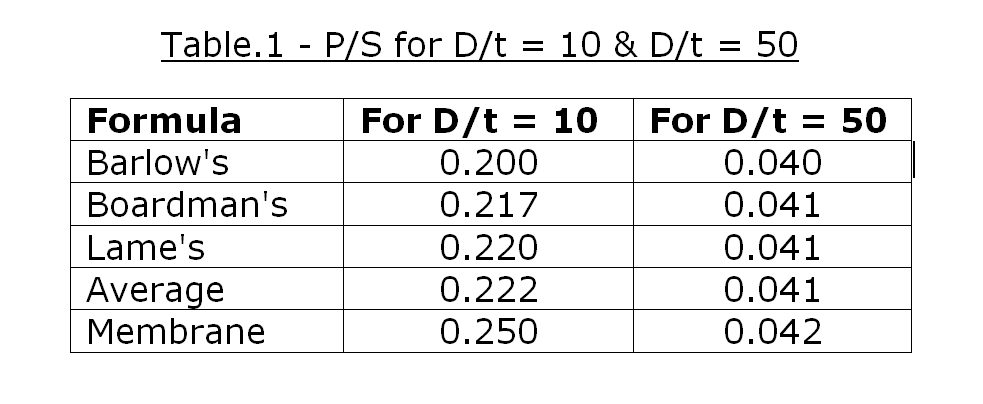
It may be noted that when D/t exceeds 50, the difference among the working pressures allowed by all five formulae discussed, becomes insignificant. Following table compares P/S values obtained from these five formulae for D/t = 10 & D/t = 50.
When the design temperature exceeds 454oC, the creep phenomenon starts playing a significant role in the determination of maximum possible stress (S) that is permitted to be induced in the boiler component. Codes usually take care of this requirement by revising the value of allowable stress, considering, the creep-based properties of the material like Creep Strength and Creep Rupture Strength.
However, there is one more phenomenon called the Stress Relaxation in the creep range operation of a boiler component, that should also be considered while limiting the maximum pressure (P) of steam that can be permitted to be carried by that boiler component. This is because a given boiler component can sustain more pressure of steam due to stress relaxation in the creep range.
ASME Power Piping Code B31.1 takes care of the stress relaxation phenomenon by increasing the value of y beyond the design temperature of 482oC, in its WPF. Thus, while at 510oC, y is revised up to 0.5 from 0.4, it is hiked further to 0.7 at 538oC and above for ferritic steels.
As IBR ignores stress relaxation phenomenon in its WPF, it uses y = 0.5 in non- creep range as well as creep range. This results in liberal values of working pressure when design temperature is in the non-creep range and conservative values of working pressure when design temperature is in the higher creep range, as compared to ASME Power Piping Code B31.1 for ferritic steels. In other words, IBR permits less working pressure of steam to be carried by a given ferritic boiler component in the higher creep range as compared to ASME Power Piping Code B31.1.
Conclusion
The Average formula adopted by IBR permits more working pressure for a given cylindrical boiler component at given design conditions as compared to ASME Boiler & Pressure Vessel Code (Section I) that has adopted a more conservative Boardman’s formula. However, it permits less working pressure for a given cylindrical boiler component at given design conditions as compared to ASME Power Piping Code B31.1 for ferritic steels in the higher creep range.
Reference
- Indian Boiler Regulations
- ASME Boiler & Pressure Vessel Code
- ANSI/ASME Power Piping Code B31.1
S. Ganesan, Director of Boilers, Tamil Nadu, Chennai – 5