Introduction
Stress analysis is often taken seriously by those who know the consequences. It is often observed that small chemical manufacturers are unaware of the purpose of stress analysis and its consequences in a chemical plant. Some even end up saying that in the olden days, there were no computers, but still old plants were working.
Some manufacturers keep facing recurring problems of leakages and vibrations in piping due to high piping stresses, but many end up living with them since they’re unaware that it’s all because of high thermal stresses in piping.
In this chapter-1 we will cover the basics of why stress analysis is important and some basics of stress analysis in simple words, and how it can impact the operations of a chemical plant. We will also share our vast experience on stress analysis in various chapters in subsequent editions, i.e. we start from the basics in simple words and slowly move to more advanced piping analysis topics.
I will share some very interesting case studies we have encountered as consultants. Before we go into the technicalities of stress analysis, we start with the very basics of why we do stress analysis.
The Purpose Of Stress Analysis Is To:
- avoid leakages due to line failure i.e. overstressing. This can be due to thermal expansion or under-supporting of piping
- avoid equipment failures. This can happen due to improper supporting near the pump or ignoring piping thermal expansion effect on the pump. This may lead to misalignment, bearing failure, seal failure and noisy operation of the pump. Impact on overloading connections on pressure vessels can be more dangerous
- ensure loads on equipment nozzles are well within vendor allowable as a guaranteed requirement
- get loads on the structure for design, this is useful during the engineering stage
- avoid facing stress analysis-related problems when the plant is in operation since any rectification requirement means a long shutdown leading to production loss.
Codes and Standards:
The widely used code for process piping is ASME B 31.3 for process piping and ASME 31.1 for power piping. On top of these, the local rules and requirements are applicable, like the IBR (Indian Boiler Regulation) for steam piping in India.
Basics of Stress Analysis:
Stress analysis is carried out to ensure stresses in piping are within the allowable limit. There are two types of stresses that are calculated and compared with allowable:
- Sustained, i.e. primary stresses
- Expansion i.e. Secondary stresses
Sustained Stresses are generated due to pressure and weight. Once pipe thickness is calculated, the field supporting the pipes will determine these sustained stress values. If lines are properly supported, they will be well within allowable limits.
Supports are normally placed within the maximum distances specified in the support spacing tables for the project.
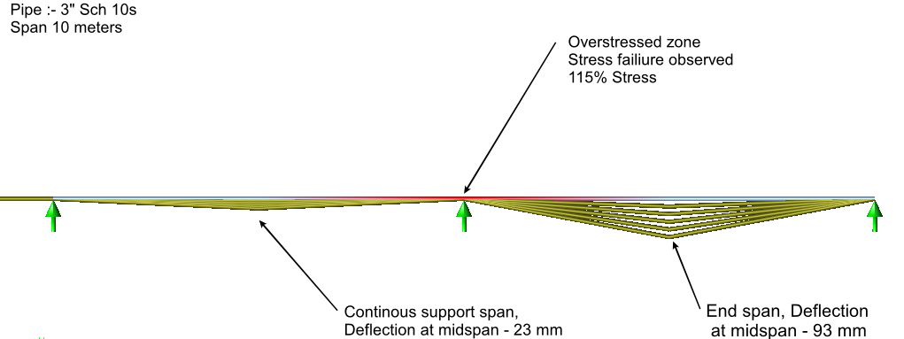
Referring to Figure-1, a case with a high span under the supporting case is shown below, which shows failure, i.e. the distance between supports is very high, leading to sagging at the centre and overstressing at the support location.
Sustained Stress: Weight Plus Pressure Stress (excluding thermal effect)
Thermal Stress: This is generated due to pure thermal expansion. Metals tend to expand when heated and all lines with hot fluid experience these stresses. Expansion depends on the temperature and length of the pipe. The higher the temperature and length, the higher the expansion of the pipe.
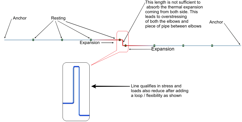
Any restriction to this thermal expansion will induce high thermal loads, which may lead to piping failure or high loads on structures. Pipes need to be routed properly by imparting sufficient flexibility to ensure that expansion stresses are within allowable limits. In Figure-2 it is seen that high stresses (red colour) are induced at the elbows due to thermal expansion since the available length (perpendicular to the major pipe length) to absorb expansion is very short as compared to the overall length. This also induces very high loads at the anchors, which can be equipment nozzles or anchors on the structure. After adding loops and imparting sufficient flexibility, it is observed that the line stress is within allowable limits.
Analysis Method And Procedure:
Stress analysis is usually carried out by experienced engineers. Currently, many engineering software programs are available on the market to perform stress analysis. Normally, lines falling under stress analysis are divided into three categories.
Cat-1 The critical lines that require a formal stress analysis using proven and widely accepted software in the industry. These are normally with high temperatures and sizes greater than 6” NB, connected to load-sensitive equipment like pumps and compressors, lines with expansion joints, etc.
Cat-2 These are less critical and require manual calculations by an experienced stress engineer.
Cat-3 These are non-critical lines, but supporting them is preferably done by an experienced stress engineer.
These categories are defined by the client/engineering consultant and criticality criteria may differ from project to project.
Importance Of Nozzle Loads And Guarantee Clause:
Normally, every equipment vendor issues allowable piping loads on equipment connections. An engineering consultant or the company buying the equipment is supposed to maintain these piping connection loads under the allowable limits given by the vendor. The guarantee of the equipment or time-specific warranty is valid only if the buyer ensures the piping calculations are performed and the loads are met within allowable limits.
In the event of malfunctioning equipment, the vendor has every right to ask for the calculation and check if the connection loads are kept within allowable limits. Failing to furnish such calculations, the equipment vendor may claim the guarantee as void and may refuse to attend to the complaint.
Critical equipment like pumps, turbines, compressors and compo block exchangers is very load sensitive, these are subjected to vibrations, flange joint leakages and other problems if piping connection loads are not maintained within allowable limits. In such cases where the guarantee is involved, it is always better to get the piping calculations done using one of the reputed software to present it to the supplier in case of a dispute.
Case Study On Nozzle Loads:
We had come across a case where the complete grassroots carbon black plant was ready and the turbine was being commissioned. The turbine-rated speed was 12000 RPM. On starting the turbine and after crossing 5500 RPM, the turbine started vibrating heavily. The turbine vendor started blaming the piping support and tried to get away, however, we offered him our calculations and convinced their piping experts that the calculations were correct and had no errors.
Finally, the turbine supplier had to admit his mistake and he took the turbine back to the factory, 500 km away from the site. Had a balancing issue, which he got resolved and installed back to see a smooth operation in the future. This finally delayed the commissioning of the completed project by a month.
Some turbine vendors prefer to check calculations, supporting loads and induced loads in advance and approve them; however, this depends on the vendor’s capability.
Author
Ashok Gupta
ND Engineering Services

Er R.Gopalakrishna FIE
September 19, 2023 at 7:28 amGood practical points about failures,These are n toot known floor engineers to known to many ,